
Image Reading Apparatus

a technology of image reading and reading apparatus, which is applied in the direction of thin material handling, instruments, article separation, etc., can solve the problems of specific area in the vicinity of the in-conveyer unit section, inability to maintain the image forming apparatus, and inability to meet the needs of the user, so as to improve the durability of the opening/closing motion of the conveyer unit, the effect of reducing the size of the image reading apparatus

Active Publication Date: 2012-03-01
BROTHER KOGYO KK
View PDF13 Cites 10 Cited by
  • Summary
  • Abstract
  • Description
  • Claims
  • Application Information

AI Technical Summary

Benefits of technology

[0009]In view of the above deficiencies, the present invention is advantageous in that an image reading apparatus, in which handling convenience for opening / closing motions of a conveyer unit is improved, is provided. Further, an entire size of the image reading apparatus is reduced, and durability for the opening / closing motions of the conveyer unit is improved.

Problems solved by technology

With the concentrated force, the area in the vicinity of the in-conveyer-unit section may be specifically exhausted or damaged whilst the conveyer unit is repeatedly opened and closed over a long period of time.
Accordingly, the image forming apparatus may not be durable over a long period of time.

Method used


Image

  • Image Reading Apparatus
  • Image Reading Apparatus
  • Image Reading Apparatus

Examples


Embodiment Construction

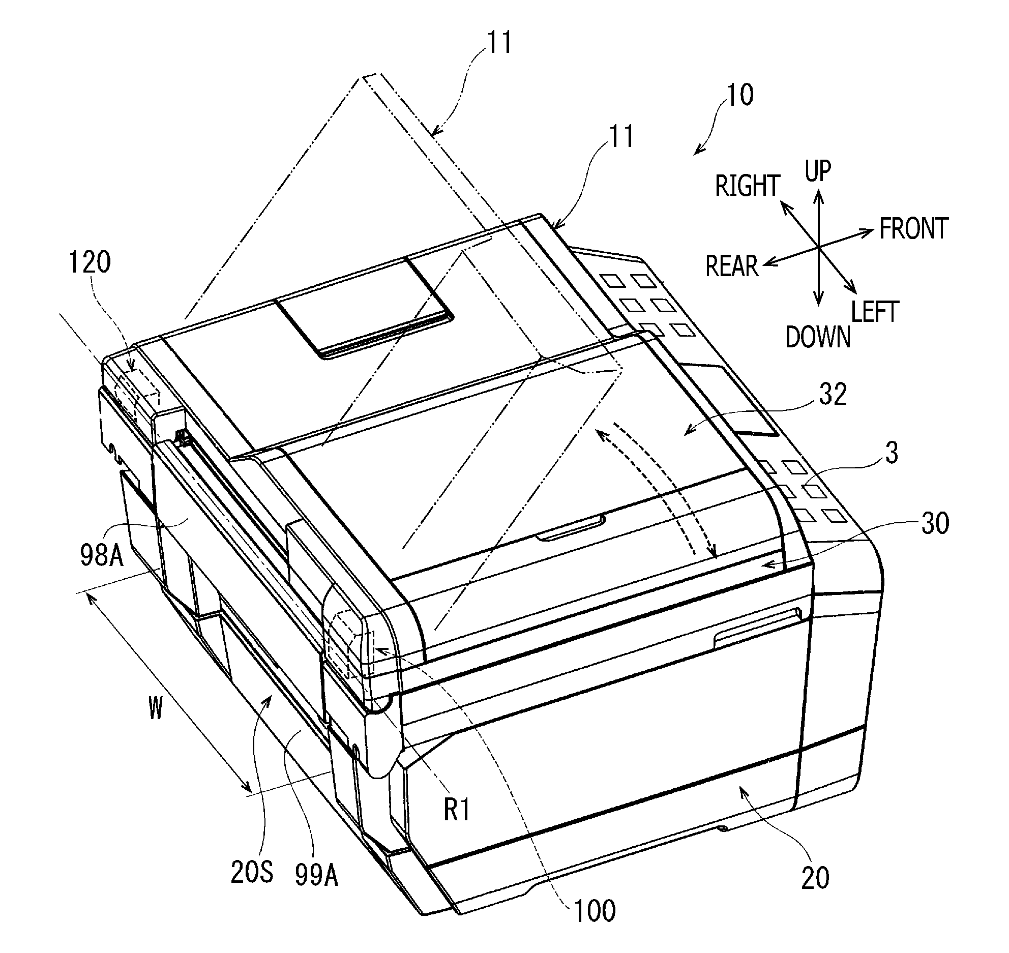
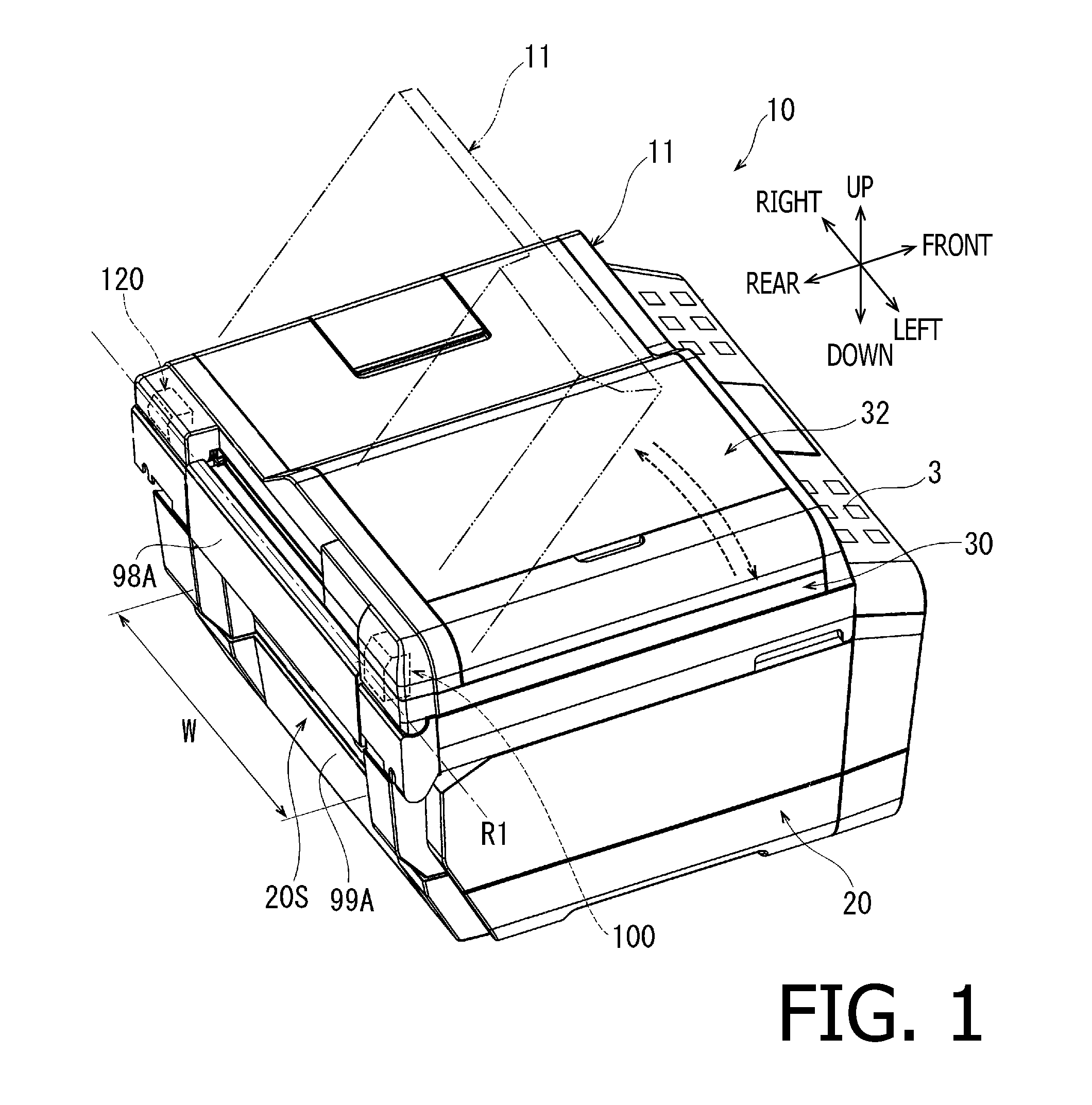
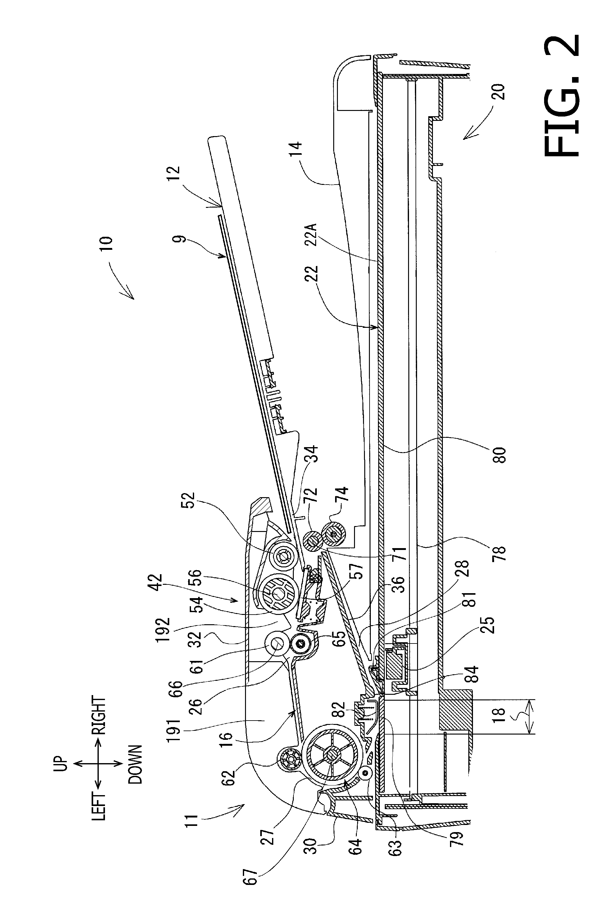
[0022]Hereinafter, an MFP 10 according to an embodiment of the present invention will be described with reference to the accompanying drawings. The MFP 10 is a multifunction peripheral device, which is capable of reading an image appearing on an original sheet, printing an image on a recording sheet, and exchanging image data with external devices.

[0023]In the description below, directions concerning the MFP 10 will be referred to based on a user's position to use the MFP 10 whilst it is assumed that the user faces a front side of the MFP 10. That is, a viewer's upper right-hand side appearing in FIG. 1 is referred to as the user's front of the MFP 10, and a lower left-hand side in FIG. 1 opposite from the front side is referred to as rear, whilst the MFP 10 has an operation panel 3 on the front side thereof. A side which corresponds to the viewer's nearer side is referred to as left, and an opposite side from the left, which corresponds to the viewer's further side, is referred to ...


PUM


Abstract

An image reading apparatus is provided. The image reading apparatus includes a main unit and a conveyer unit swingably coupled to the main unit via a hinge. The conveyer unit includes a lower cover with an opening, which extends orthogonally to a swing axis of the conveyer unit, and an attachable member. The attachable member includes a main part and an auxiliary part and is fixed to the lower cover by the main part and to a rotatable fixing section of the hinge by the auxiliary part.

Description

CROSS REFERENCE TO RELATED APPLICATION[0001]This application claims priority from Japanese Patent Application No. 2010-191715, filed on Aug. 30, 2010, the entire subject matter of which is incorporated herein by reference.BACKGROUND[0002]1. Technical Field[0003]An aspect of the present invention relates an image reading apparatus.[0004]2. Related Art[0005]An image reading apparatus having a main unit and a conveyer unit on top of the main unit is known. The main unit may include a flatbed, on which a sheet of original document to be read is placed, and an image reader, which is movable along the flatbed in a range from one side to the other side of the flatbed. Whilst being moved along the flatbed, the image reader scans and read an image appearing on the sheet.[0006]In the image reading apparatus, the conveyer unit may be coupled to the main unit via hinges to be swingable about a swing axis, which extends in parallel with the moving direction of the image reader. The hinge may inc...

Claims


Application Information

Patent Timeline
Patent Type & Authority Applications(United States)
IPC IPC(8): H04N1/04
CPCH04N2201/0081H04N1/00554H04N1/193H04N1/12H04N1/1013
Inventor IWATA, NAOYUKITAKAMI, TAKESHI
Owner BROTHER KOGYO KK
Learn More