

X-ray fluorescence analyzer and x-ray fluorescence analysis method
- Summary
- Abstract
- Description
- Claims
- Application Information
AI Technical Summary
Benefits of technology
Problems solved by technology
Method used
Image

Examples
first embodiment
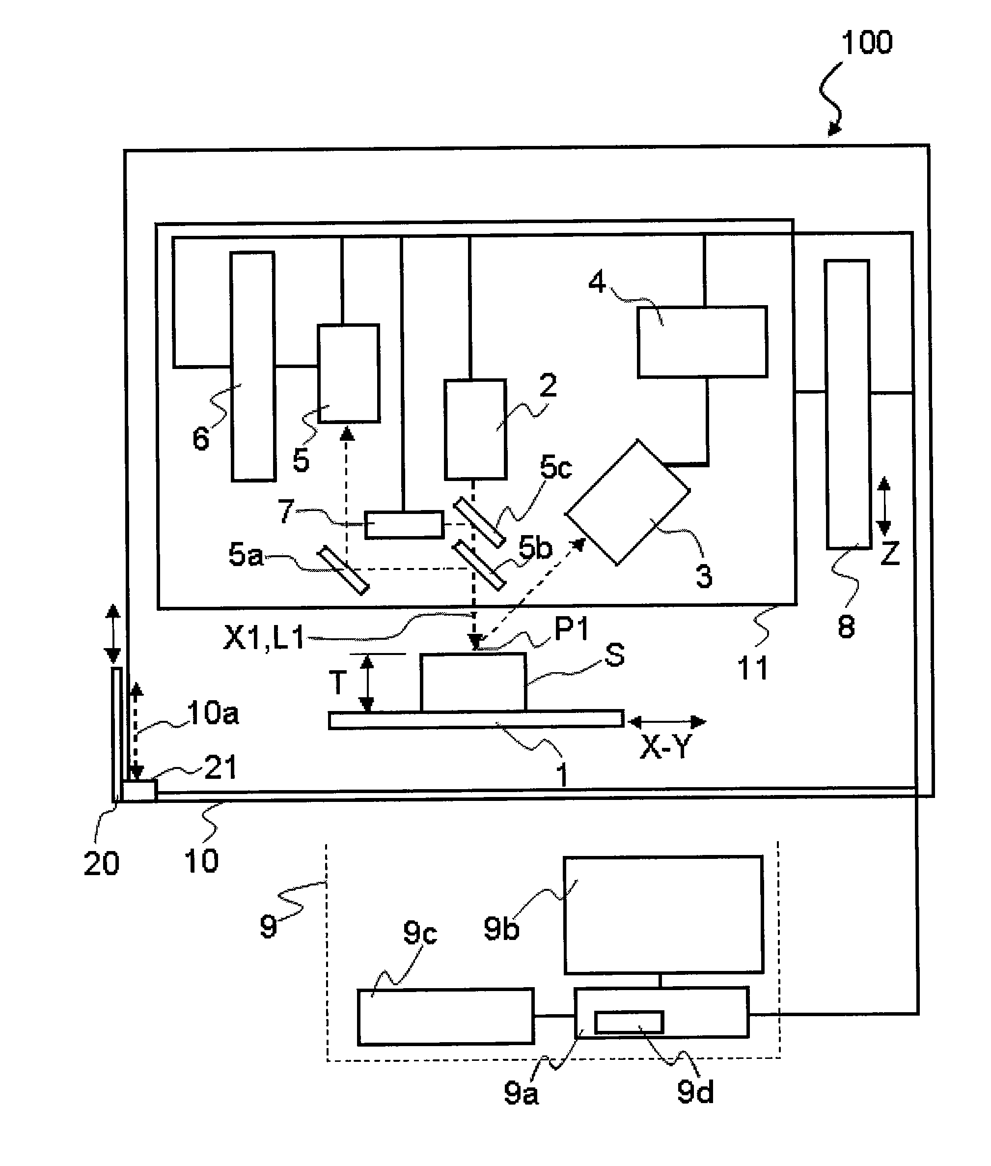
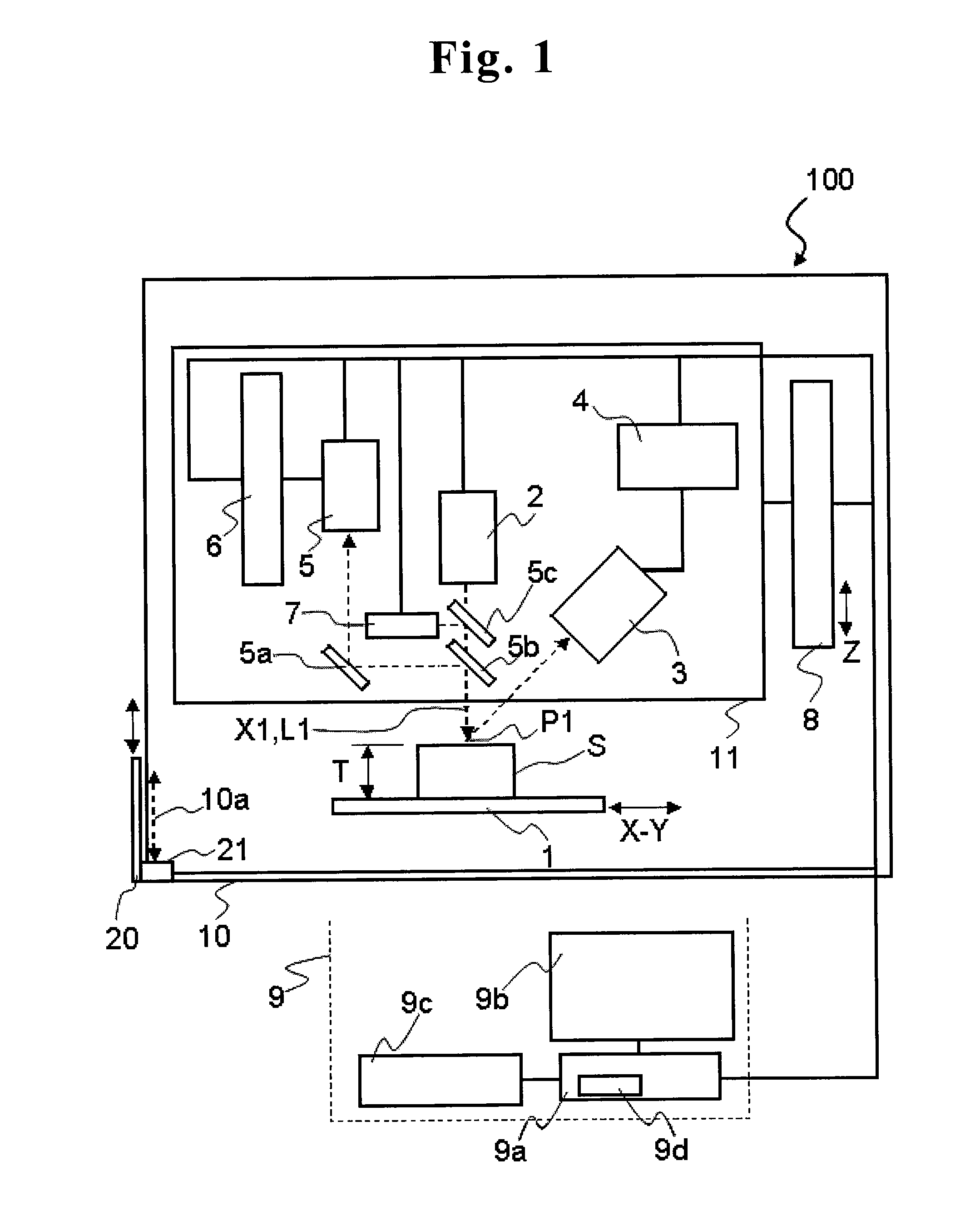
[0045]FIG. 1 is a block diagram illustrating a structure of an X-ray fluorescence analyzer 100 according to the present invention. The X-ray fluorescence analyzer 100 is an energy dispersive X-ray fluorescence analyzer, for example, which includes a sample stage 1 on which a sample S is placed, an X-ray tube (radiation source) 2, an X-ray detector 3, an analyzer 4, an observation system 5, a focus switching drive mechanism 6, a laser unit 7, a measurement head moving mechanism 8, and a control computer 9 (corresponding to “moving mechanism control unit”, “laser start control unit”, “height measurement mechanism start control unit”, and “observation system focus control unit” in claims).
[0046]In addition, each component of the X-ray fluorescence analyzer 100 (except the control computer 9) has a structure for preventing leakage of X-ray to the outside of the apparatus. Further, an enclosure 10 is provided with an opening 10a so that the sample S is put into or out of the enclosure 10...
second embodiment
[0087]FIG. 8 illustrates a control flow (flow for positioning and distance measurement) performed by the control computer 9x in the
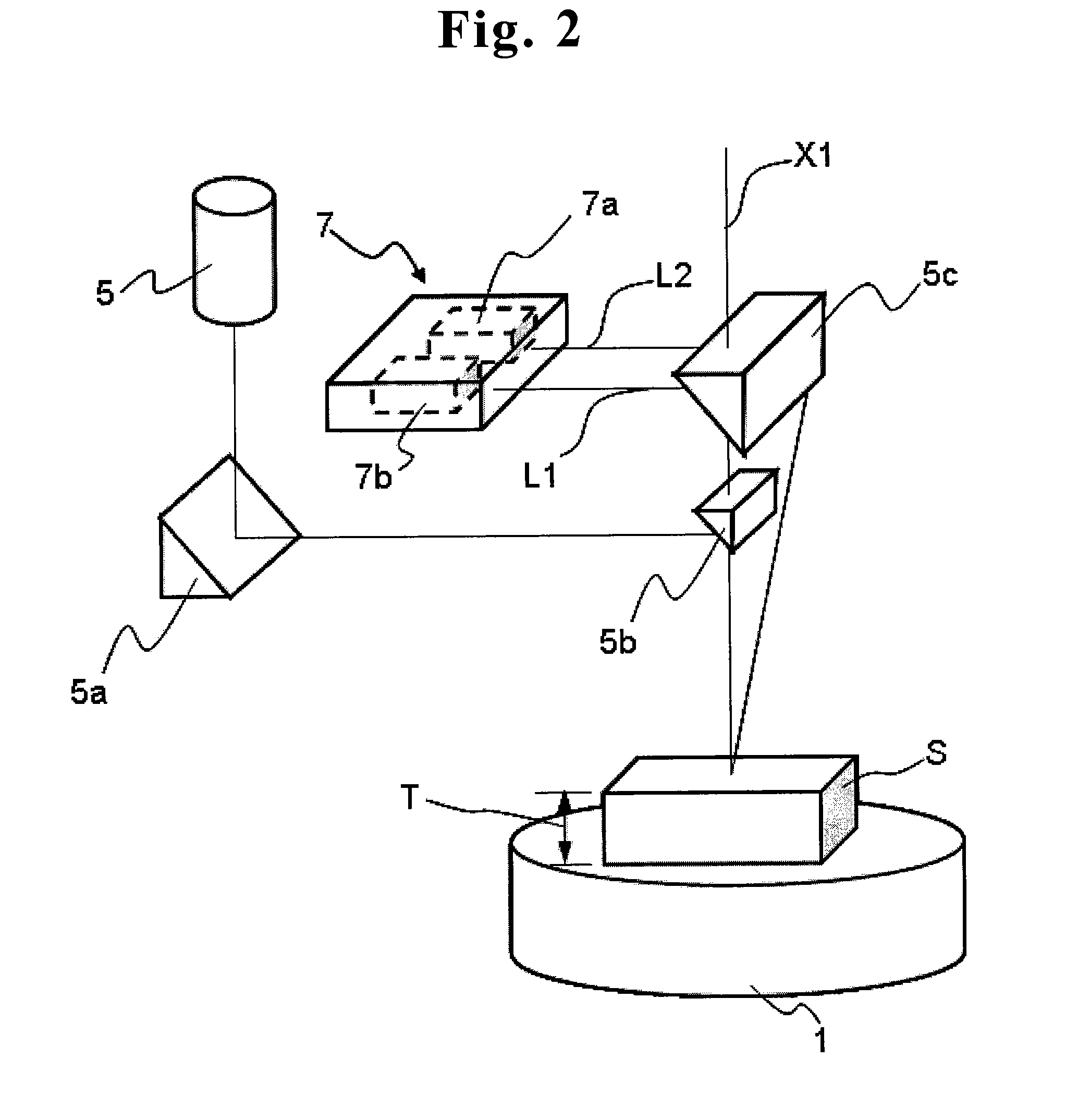
[0088]First, the control computer 9x obtains detection information from the door open / close detection unit 21 to determine whether or not the door 20 is opened (Step S101). If the determination is “Yes” in Step S101, the control computer 9x starts the first laser unit 7 so that the visible light laser beam irradiates the irradiation point P1 (Step S103). The first laser unit 7 receives the secondary laser beam L2 generated from the irradiation point P1, and obtains information of the distance (height T of the sample S from the sample stage 1), which is sent to the control computer 9x.
[0089]The control computer 9x calculates the difference D based on the obtained information of the height T at the irradiation point P1, and starts the measurement head moving mechanism 8 so that the difference D is canceled (Step S105). In this way, the irradiation point P...
PUM
 Abstract
Description
Claims
Application Information