Apparatus for self-phase modulation noise calculation, apparatus for self-phase modulation noise elimination and optical coherent receiver

a self-phase modulation and noise elimination technology, applied in the field of optical communication, can solve the problems of higher calculation complexity, and achieve the effect of reducing the complexity of the calculation of self-phase modulation and the hardware implementation of the apparatus for self-phase modulation noise elimination

Active Publication Date: 2012-03-01
FUJITSU LTD
View PDF2 Cites 13 Cited by
  • Summary
  • Abstract
  • Description
  • Claims
  • Application Information

AI Technical Summary

Benefits of technology

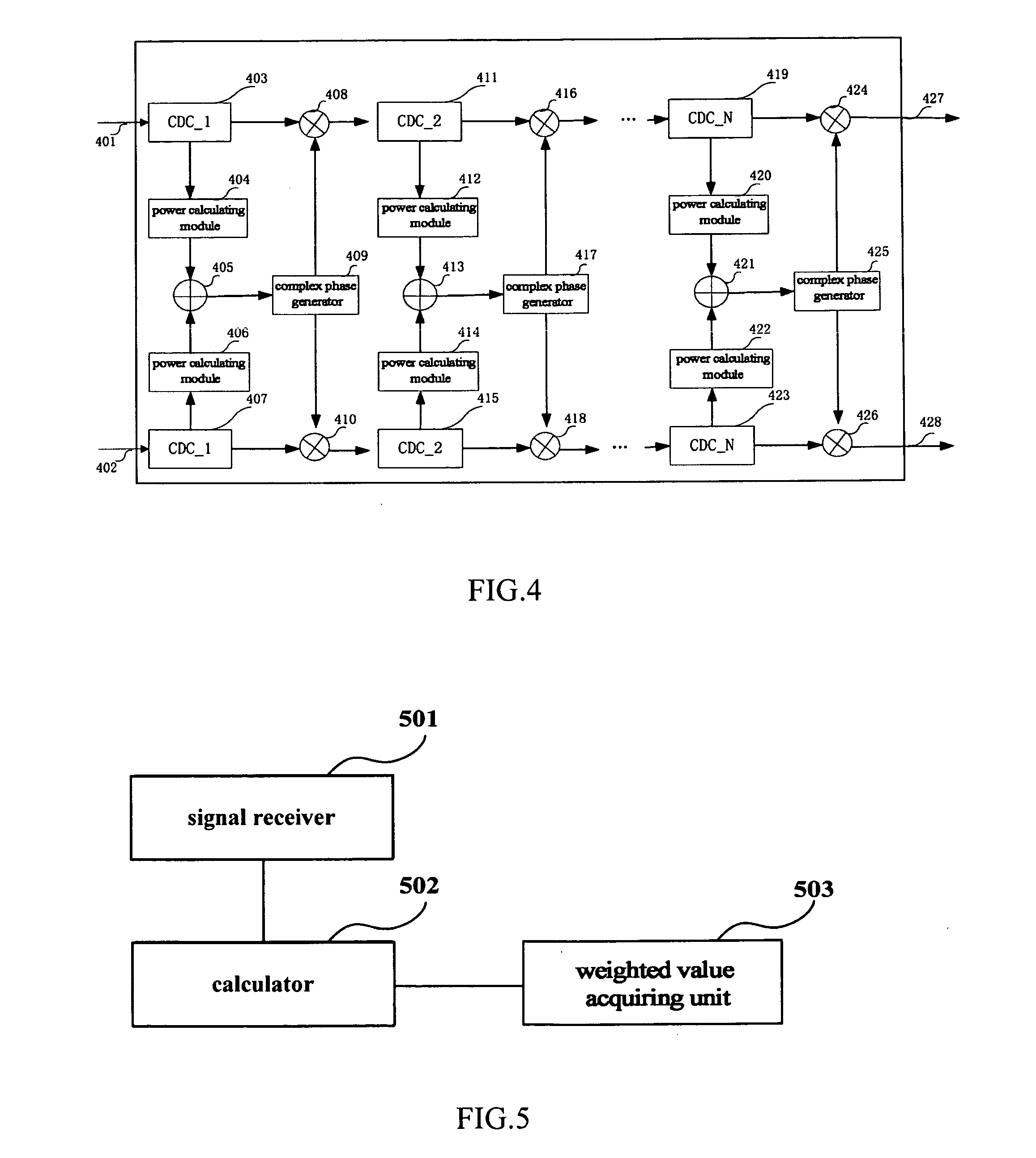
[0007]In the embodiments of the present invention, when a self-phase modulation is performed, it comprises the steps of: receiving an input signal; calculating a self-phase modulation noise at the current instant by using the signal powers of an input signal waveform at the current instant and at several sampling instants adjacent to the current instant. Thus, by combining and calculating signal powers at a plurality of sampling periods, in case that a certain precise is ensured, when the self-phase modulation noise of the input signal on an optical fiber transmission link is calculated by using the above-mentioned method, the granularity of the sub-spans may be relatively large, thereby reducing the calculation complexity of the self-phase modulation.
[0012]In the embodiments of the present invention, the following method is adopted to eliminate the self-phase modulation noise:
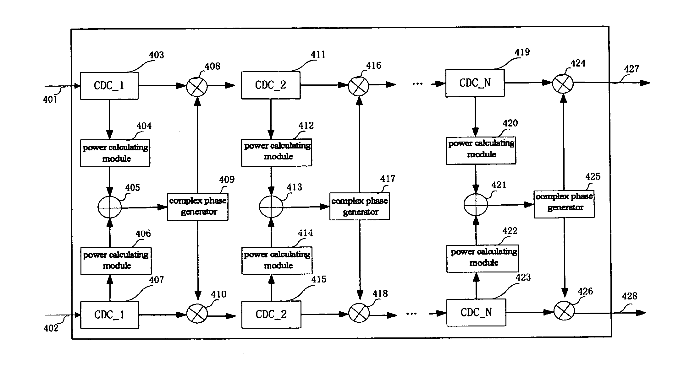
[0014]processing the received baseband electric signal step by step to eliminate an adaptive modulation noise; wherein in each step of the processing, the signal powers, at the current instant and at several sampling instants adjacent to the current instant, of the electrically dispersion compensated signal waveform in current step, are used to calculate the self-phase modulation noise at the current instant and obtain the inverse number of the self-phase modulation noise, and the inverse number of the self-phase modulation noise is converted into a complex form, which is multiplied by the electrically dispersion compensated signal waveform in the current step to eliminate the self-phase modulation noise in the current step;
[0016]It can be seen from above that, by combining and calculating signal powers at a plurality of sampling periods, in the case that a certain precision is ensured, the cascade number of the electric dispersion compensation modules in the apparatus for self-phase modulation noise elimination may be reduced and the complexity of the hardware implementation of the apparatus for self-phase modulation noise elimination may be also reduced.
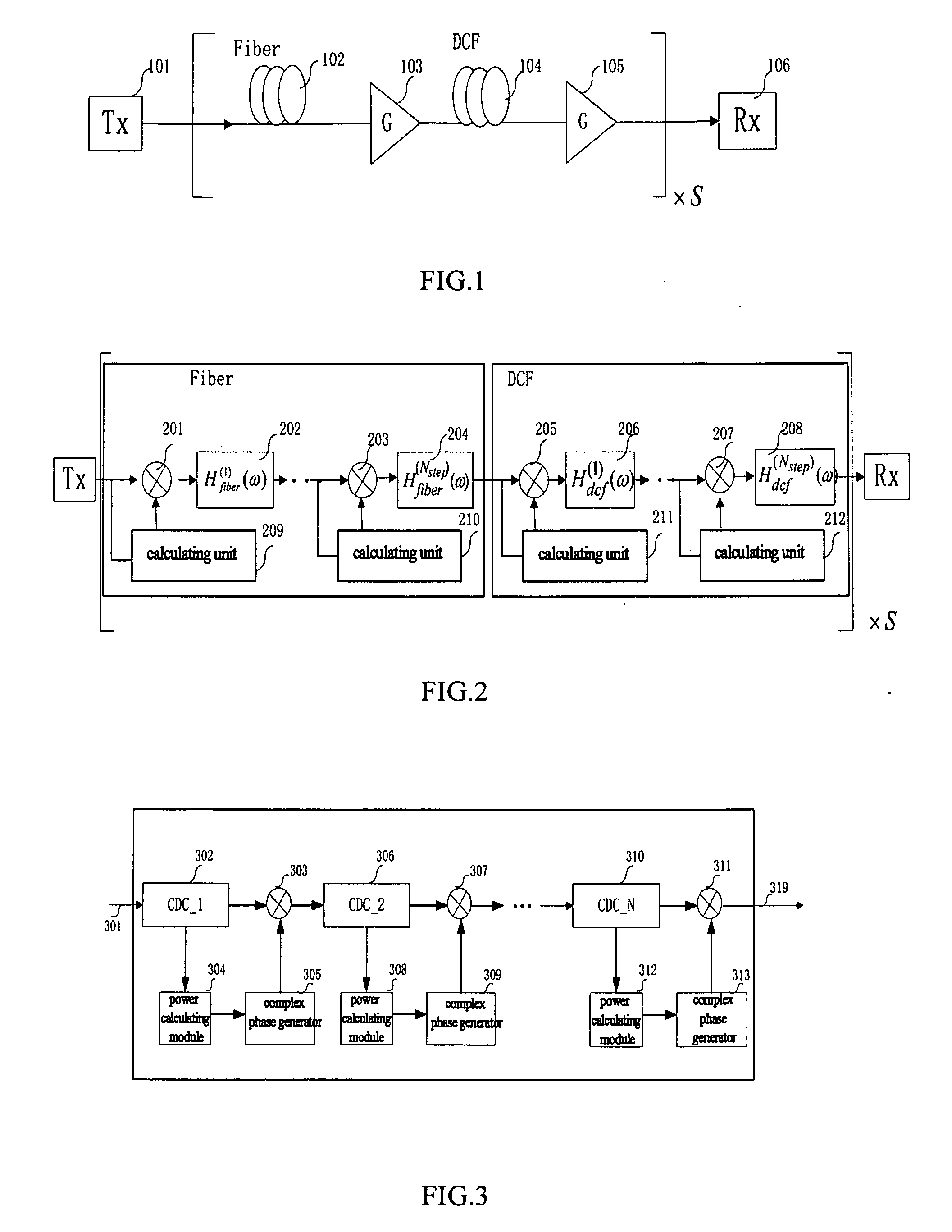
[0018]The advantages of the embodiments of the present invention exist in: when the apparatus for self-phase modulation noise calculation calculates the self-phase modulation at a certain instant, not only the signal power at this instant, but the signal powers at a plurality of digital sampling periods before and after the certain instant are also considered. In this way, when the apparatus is applied to the optical fiber transmission system shown in FIG. 1, by combining and calculating signal powers at a plurality of sampling periods, in case that a certain precision is ensured, the granularity of the sub-spans is made to be relatively large, thereby reducing the complexity of the calculation of the self-phase modulation; and when the apparatus is applied to the apparatus for self-phase modulation noise elimination, the cascade number of the electric dispersion compensation modules in the apparatus for self-phase modulation noise elimination is reduced and the complexity of the hardware implementation of the apparatus for self-phase modulation noise elimination is also reduced.

Problems solved by technology

The finer the granularity is, the higher the precision of the calculation, but the higher the complexity of the calculation.

Method used


Image

  • Apparatus for self-phase modulation noise calculation, apparatus for self-phase modulation noise elimination and optical coherent receiver
  • Apparatus for self-phase modulation noise calculation, apparatus for self-phase modulation noise elimination and optical coherent receiver
  • Apparatus for self-phase modulation noise calculation, apparatus for self-phase modulation noise elimination and optical coherent receiver

Examples


example 1

[0069]the weighted value acquiring unit 503 acquires the weighted value sequence wi by monitoring the correlation degree in time domains between the self-phase modulation noise and the signals at adjacent instants;

[0070]in the case as above, as shown in FIG. 8, the weighted value acquiring unit 503 may comprise:

[0071]a first receiver 801 to receive a signal containing a self-phase modulation noise which is a single-polarization or dual-polarization signal;

[0072]a first deciding unit 802 to decide the signal received by the first receiver 801 with respect to data, so as to acquire a signal containing no self-phase modulation noise;

[0073]a first calculator 803 to calculate the weighted value sequence by using the signal received by the first receiver 801, the signal obtained by the first deciding unit 802 after data decision, and the signals at the ith and the (i+N)th instants prior to the current instant; where, N is a predetermined integer greater than or equal to 0 (dual-polarizati...

example 2

[0080]the weighted value acquiring unit 503 acquires the weighted value wi sequence in a process in which it seriatim assumes one or more of the weighted value wi sequence and seriatim determines the corresponding values at the optimal performance of the equipment used in the apparatus after several times determination.

[0081]For example, when the apparatus is applied to the apparatus for self-phase modulation noise elimination in an optical coherent receiver, for k instants before and after the current instant t, for instance, k=4, the weighted values respectively correspond to w−4, w−3, w−2, w−1, w0, w1, w2, w3 and w4; first, assume one of the values, such as w0, and other values are 0, and then adjust w0, the assumed w0 at the optimal performance of the receiver is the acquired weighted value w0; then assume other weighted values in turn while keeping the determined acquired weighted value w0 constant, and acquire other weighted values w−4, w−3, w−2, w−1, w1, w2, w3 and w4 in the ...

example 3

[0082]the weighted value acquiring unit 503 can assume the function satisfied by the weighted value wi sequence, and determines the corresponding coefficient at the optimal performance of the equipment used in the apparatus by alternating the coefficient of the function to acquire the weighted value wi sequence.

[0083]For example, when the function satisfied by the form of the weighted value wi sequence is an exponential function, i.e. wi=exp(αiT), where, α is the coefficient of the exponential function, i represents the ith instant, and T represents the sampling period, change the numerical value of α while monitoring the optimal performance of the equipment used in the apparatus; and when the modulator is applied to the apparatus for self-phase modulation noise elimination in an optical coherent receiver, the corresponding value of α is optimal when the performance of the receiver is optimal, thereby acquiring the weighted value sequence according to the exponential function corres...


PUM


Abstract

The present invention provides apparatus for self-phase modulation noise calculation, apparatus for self-phase modulation noise elimination and optical coherent receiver. The apparatus for calculation comprises: a signal receiver to receive an input signal; a calculator connected to the signal receiver to calculate a self-phase modulation noise at the current instant by using the signal powers of an input signal waveform at the current instant and at several sampling instants adjacent to the current instant. The embodiments of the present invention calculates the self-phase modulation noise at a certain instant by using the signal powers at a plurality of digital sampling periods before and after this instant, and when the apparatus is used to calculate the self-phase modulation noise of each of the sub-spans in an optical fiber transmission link, in case that the calculation precision is ensured, the granularity of the sub-spans may be reduced, thereby lowering the complexity of the calculation.

Description

CROSS REFERENCE TO RELATED APPLICATIONS[0001]This application claims the benefit of Chinese Application No. 201010270816.8, filed Aug. 31, 2010, the disclosure of which is incorporated herein by reference.TECHNICAL FIELD[0002]The present invention relates to the field of optical communications.BACKGROUND OF THE INVENTION[0003]The nonlinear noise of a fibre channel mainly comprises the self-phase modulation (SPM) noise caused by the fluctuations of the signal power of its own channel, and cross-phase modulation (XPM) noise caused by the fluctuations of the signals power of adjacent channels. For the self-phase modulation noise generated by a signal after being transmitted in a span of fiber, its numerical value may be calculated based on the power of the signal transmitted in this span of fiber. And for the self-phase modulation noise of the whole transmission link, due to the fiber dispersion in the transmission link, the power of the signal being transmitted changes along with the ...

Claims


Application Information

Patent Timeline
Patent Type & Authority Applications(United States)
IPC IPC(8): H04B10/08H04B10/04H04B10/00H04B10/06H04B10/2507H04B10/07H04B10/255
CPCH04B10/0795H04B10/6163H04B10/255
Inventor LI, LEITAO, ZHENNINGHOSHIDA, TAKESHI
Owner FUJITSU LTD
Why Eureka
Try Eureka