Flow battery systems

a battery and flow technology, applied in the field of electrochemical cells, can solve the problems of gas evolution, non-uniform metal build-up over many charge/discharge cycles, energy lost while plating this metal, etc., and achieve the effects of high battery charge rate, uniform metal plating, and high cell current density

Active Publication Date: 2012-03-01
APPLIED MATERIALS INC
View PDF8 Cites 101 Cited by
  • Summary
  • Abstract
  • Description
  • Claims
  • Application Information

AI Technical Summary

Benefits of technology

[0011]In many embodiments described herein, the cathodic wires are disposed perpendicular to the flow path of the electrolyte (e.g., catholyte) which provides many performance improvements for the flow battery cells. The cathodic wires generally produce more uniform metal plating when compared to traditional planar electrodes. The flow battery system generally has a higher cell current density while keeping the current density on the cathodic wires reasonable (e.g., a low fraction of the limiting current)—which in turn leads to a higher battery charge rate relative to a traditional battery. The flow battery system containing a plurality of cathodic wires generally has a larger metal storage capacity leading to larger discharge times at a given current density, relative to traditional flow batteries. The sequential plating of various arrays of cathodic wires helps to achieve longer discharge times for the flow battery system, as well as to provide in-situ electrode maintenance to avoid downtime for electrode reconditioning—as compared to a traditional planar electrode. For example, when deplating off one array of cathodic wires, another array of cathodic wires may have a small trickle discharge to insure complete or near complete removal of the plated metal. The cathodic wires provide plating and deplating rates which generally are more uniform and yield good performance over many charge / discharge cycles—as compared to a traditional planar electrode. The cathodic wires yield a large surface area with a relative low volume of metal contained therein. The large surface area of the cathodic wires typically provides lower cell voltage drop and higher cell efficiency—as compared to a traditional planar electrode. In some examples, the surfaces of the cathodic wires contain cadmium, such as a solid cadmium wire, a cadmium coated steel wire, or the like and the catholyte contains metal ions (e.g., zinc ions) which are electrochemically reduced and plated onto the cathodic wires as a metal film (e.g., metallic zinc) during a charge cycle.

Problems solved by technology

For example, metal plated with a morphology that has poor adhesion may fall off the planar electrode before the electrical discharge and the energy stored while plating this metal would be lost.
Furthermore, a current density distribution created during plating (e.g., metal thickness uniformity) that is different than the current density obtained during the discharge leads to non-uniform metal build-up over many charge / discharge cycles.
As a result, the metal will be depleted down to the electrode in some regions and not in others, possibly leading to gas evolution, higher cell potentials, and / or reduced battery efficiency.
Flaked or deplated metal particles which accumulate in the battery cell may block the electrolyte flow paths or channels, enter and contaminate the electrolyte membrane, or cause other problematic issues—if left without intervention (e.g., removal of the flaked metal).
Similarly, metal plated onto certain portions of the electrode and not subsequently deplated may build up over many charge cycles of the battery causing issues such as flow blockage, shorting, or membrane damage.
Additionally, the compact nature of a typical flow battery cell generally creates challenges to obtaining optimal plating performance.
As a result, the flow path for the electrolyte is restricted to a narrow channel which makes it difficult to provide a uniform, high rate of ion replenishment across a large surface area electrode.

Method used


Image

  • Flow battery systems
  • Flow battery systems
  • Flow battery systems

Examples


Embodiment Construction

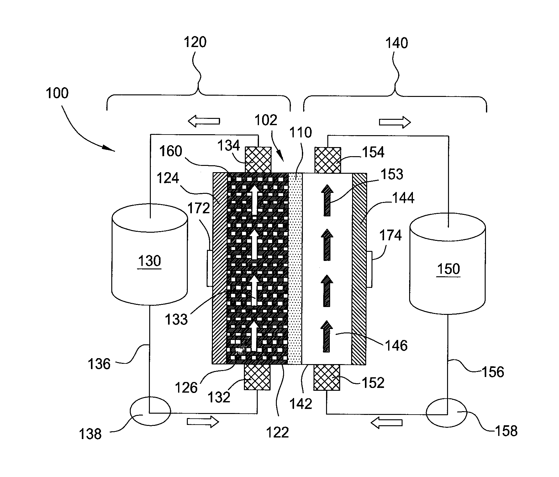
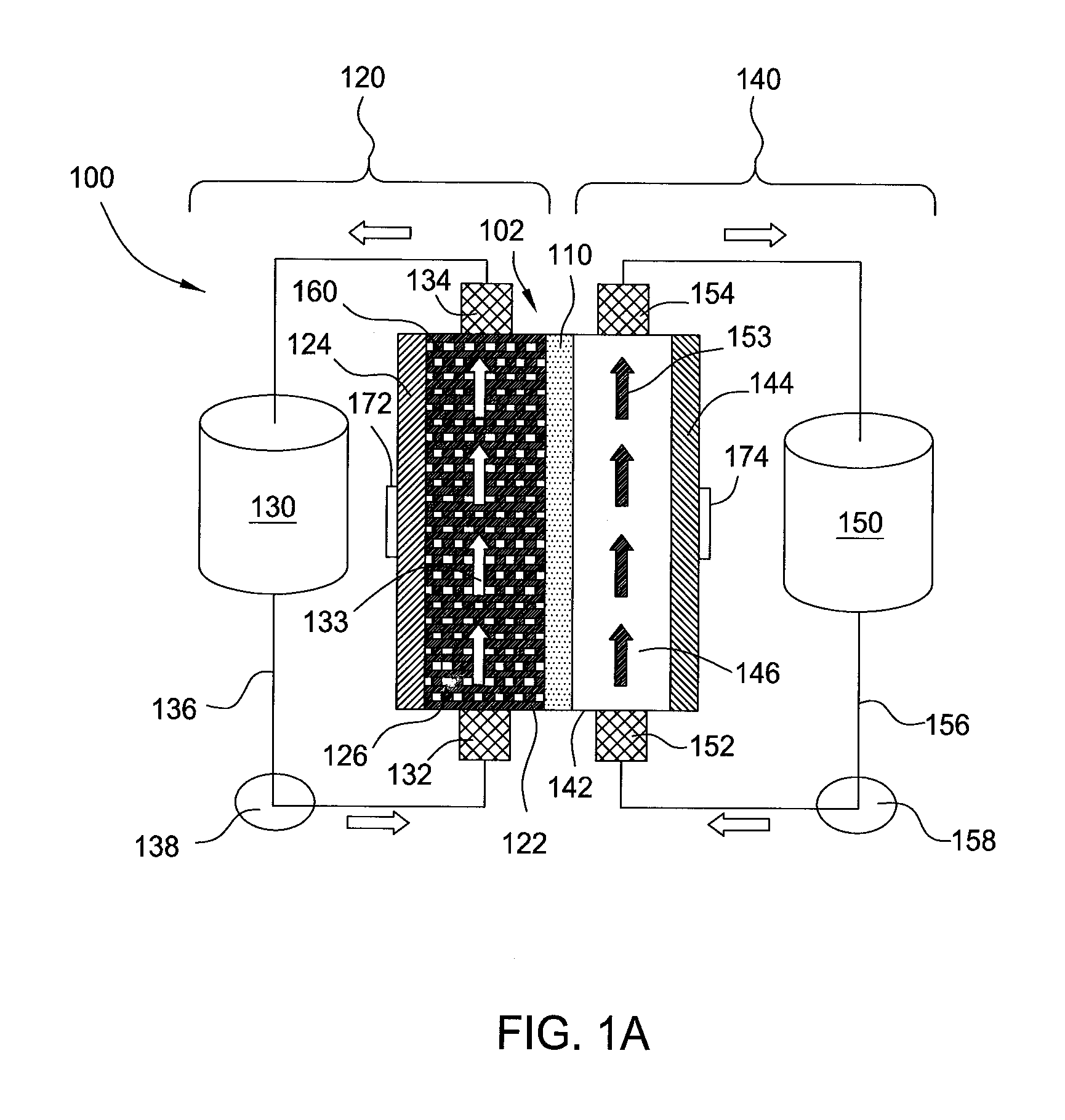
[0025]Embodiments of the invention generally provide for flow battery cells, flow battery systems containing a plurality of flow battery cells, and methods for improving metal plating on to a variety of different types of cathodes within the flow battery cell. The flow battery cells described herein have improved cathodes and electrolyte flow paths and therefore provide increased rates for plating metal, uniformity, and morphology over traditional flow batteries. In embodiments described herein, the electrode on which metal is plated may be referred to as the cathode and the same half-cell is called the cathodic side during a charging cycle of the battery. However, the current flow in the battery is reversed and the electrode on which the metal was plated becomes an anode during a discharge cycle of the battery.

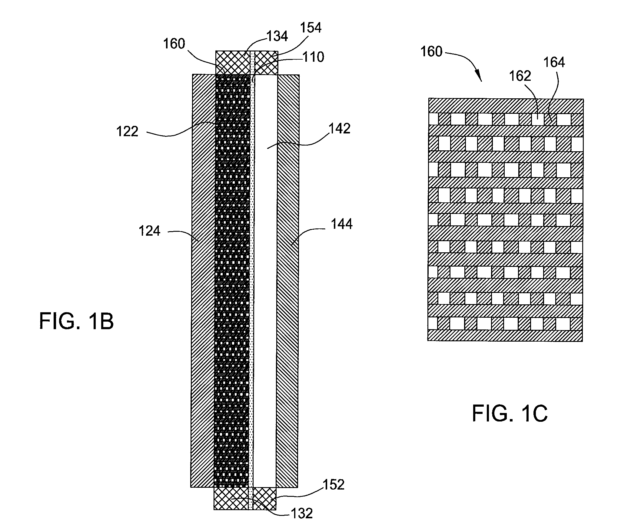
[0026]In one embodiment, flow battery system 100 contains a flow battery cell 102 which has a cathodic half cell 122 and an anodic half cell 142 separated by electrolyte memb...


PUM

PropertyMeasurementUnit
lengthaaaaaaaaaa
lengthaaaaaaaaaa
thicknessaaaaaaaaaa

Abstract

Embodiments of the invention generally provide for flow battery cells and systems containing a plurality of flow battery cells, and methods for improving metal plating within the flow battery cell, such as by flowing and exposing the catholyte to various types of cathodes. In one embodiment, a flow battery cell is provided which includes a cathodic half cell and an anodic half cell separated by an electrolyte membrane, wherein the cathodic half cell contains a plurality of cathodic wires extending perpendicular or substantially perpendicular to and within the catholyte pathway and in contact with the catholyte, and each of the cathodic wires extends parallel or substantially parallel to each other. In some examples, the plurality of cathodic wires may have at least two arrays of cathodic wires, each array contains at least one row of cathodic wires, and each row extends along the catholyte pathway.

Description

BACKGROUND OF THE INVENTION[0001]1. Field of the Invention[0002]Embodiments of the invention generally relate to electrochemical cells and more particular to flow battery cells and systems.[0003]2. Description of the Related Art[0004]Flow batteries containing electrochemical cells have been around for several decades and are used to store electrical energy. Although a variety of flow batteries exist in the art, a couple of known types of flow batteries include the zinc-ferrocyanide battery and the zinc-bromide battery. When these types of battery cells are charged, a metal (e.g., zinc) is plated onto a planar electrode within the battery cell. For an efficient battery cell, the metal should be plated at an acceptable rate, uniformity, volume, and morphology. An important aspect with flow batteries is that all or substantially all of the metal plated onto the planar electrode is available for deplating during the discharge of the battery cell. For example, metal plated with a morphol...

Claims


Application Information

Patent Timeline
Patent Type & Authority Applications(United States)
IPC IPC(8): H01M2/38
CPCH01M8/0232H01M8/0245H01M8/188H01M8/20H01M12/08H01M2250/00H01M4/42H01M8/186Y02E60/528Y02E60/10Y02E60/50
Inventor WILSON, GREGORY J.HANSON, KYLE M.
Owner APPLIED MATERIALS INC
Why Eureka
Try Eureka