Knotless suture anchor

Active Publication Date: 2012-03-01
DEPUY SYNTHES PROD INC
View PDF5 Cites 17 Cited by
  • Summary
  • Abstract
  • Description
  • Claims
  • Application Information

AI Technical Summary

Benefits of technology

[0004]The present invention overcomes these and other lim

Problems solved by technology

This reduces trauma to the patient but makes attachment of the suture to the anchor using a knot more difficult.
While such anchors work well their complexity increases m

Method used


Image

  • Knotless suture anchor
  • Knotless suture anchor
  • Knotless suture anchor

Examples


Embodiment Construction

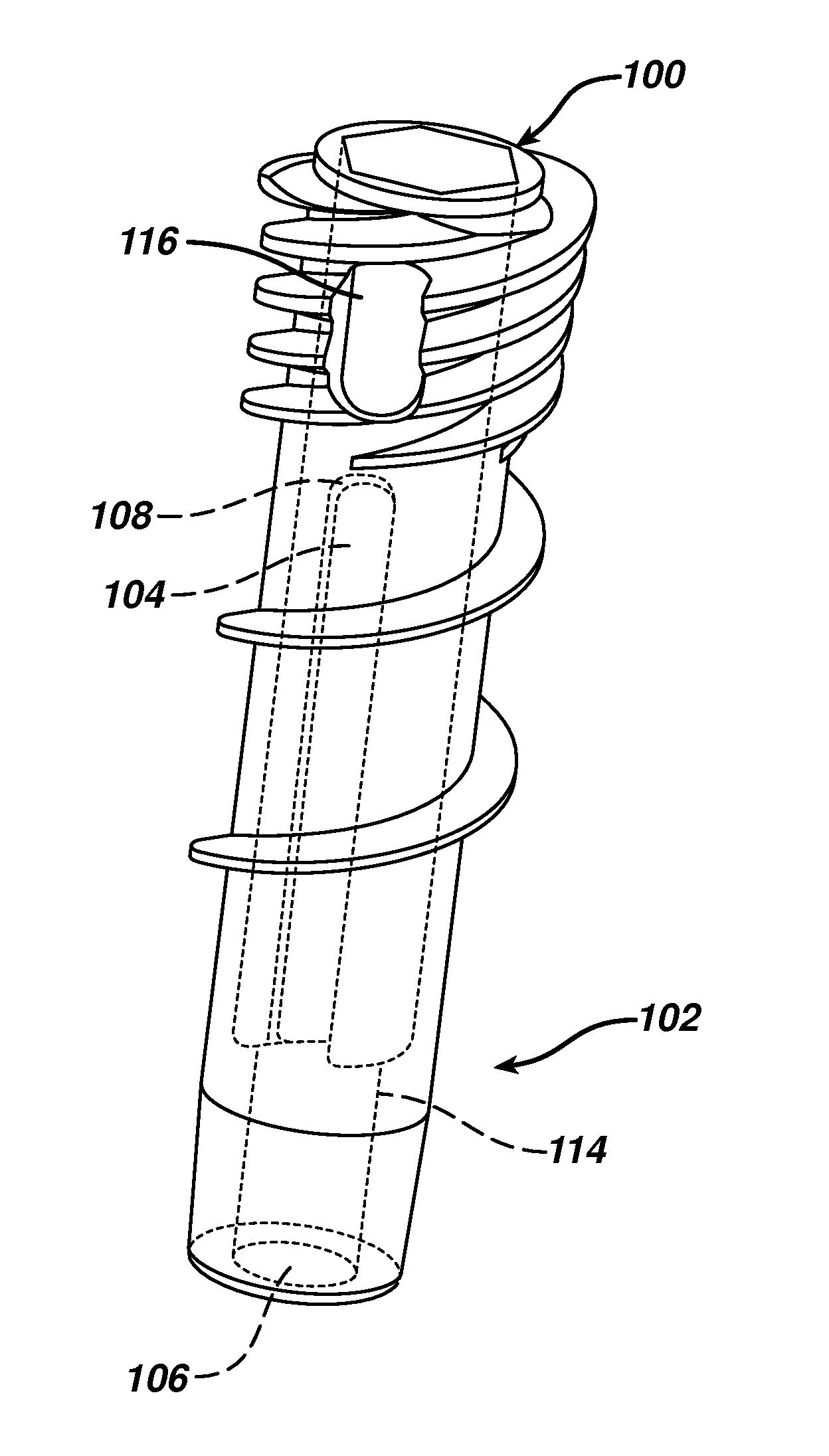
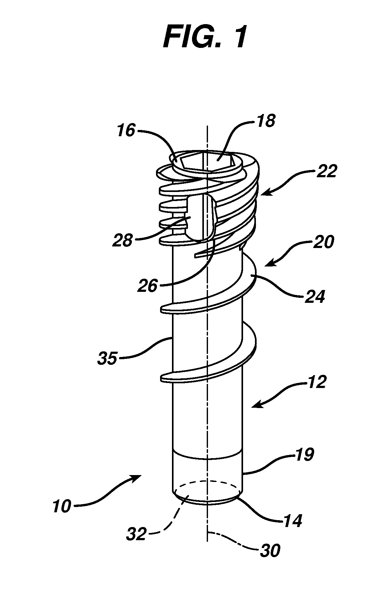
[0039]FIG. 1 depicts a knotless suture anchor 10 according to the present invention. It comprises a body 12 having a distal end 14 and proximal end 16. The proximal end 16 has a hexagonal-shaped tool receiving recess 18. It will be understood to one of skill in the art that alternative tool engagements may be employed. A slight inward taper 19 is provided at the distal end 14 to ease insertion of the anchor 10 into a bone hole (not shown in FIG. 1) and provides an initial fixation of the suture (not shown in FIG. 1) prior to threading the anchor into the hole.

[0040]The body 12 has a distal threaded portion 20 and a proximal threaded portion 22. A single exterior thread 24 threads about the body 12 to form the distal threaded section 20. This thread 24 extends nearly to the distal end 14, ending about 0.1 to 0.3 inches short thereof for easier insertion into a bone hole (not shown in FIG. 1). However, one or more additional thread leads 26 begin towards the proximal end 16 to form a ...


PUM


Abstract

A suture anchor comprises a tubular body having an axial bore therethrough and having one or more purchase enhancements on an exterior surface of the body adapted to enhance purchase of the body within a bone hole, such as threads. A lateral port passes through the body from the bore to the exterior surface. A length of suture for attaching soft tissue to bone passes down along the exterior surface over the one or more purchase enhancements, over a distal end of the body, up into the bore through and then back out of the bore and up along the exterior surface over the one or more purchase enhancements.

Description

BACKGROUND[0001]This application relates to suture anchors and more particularly to knotless suture anchors.[0002]Suture anchors are commonly employed to attach soft tissue such as tendons or ligaments to bone. For instance, in a rotator cuff repair suture is passed through a detached or damaged portion of a rotator cuff tendon. A suture anchor is implanted into the adjacent bone. By attaching the suture to the anchor the tendon is pulled into contact with the bone to promote adhesion of the tendon to the bone.[0003]Such procedures are often performed arthroscopically through a narrow cannula. This reduces trauma to the patient but makes attachment of the suture to the anchor using a knot more difficult. Knotless suture anchors may be employed which allow a surgeon to tension the suture to a desired degree and then affix to suture to the anchor without having to tie a knot. A typical knotless anchor is shown in US Patent Publication No. 20080033460 wherein the suture is trapped betw...

Claims


Application Information

Patent Timeline
IPC IPC(8): A61B17/04
CPCA61B17/0401A61B17/0485A61B17/863A61B2017/00004A61B2017/0409A61B2017/0496A61B2017/0445A61B2017/0451A61B2017/0456A61B2017/0458A61B2017/044
Inventor SOJKA, ERIK SEBASTIANSTEPHEN, ARTHUR G.FRANCISCO-GUILHERME, ANDREWOLFSON, MARK W.ORTRANDO, BRIAN HENRIGAMACHE, DANIEL PAULPICCIRILLO, JUSTIN M.LOFTON, KAIRIREISER, WILLIAMPARRISH, JEFF
Owner DEPUY SYNTHES PROD INC
Why Eureka
Try Eureka