
Fishing Lures

Inactive Publication Date: 2012-03-08
CAMILLERI CLAYTON
View PDF10 Cites 1 Cited by
  • Summary
  • Abstract
  • Description
  • Claims
  • Application Information

AI Technical Summary

Benefits of technology

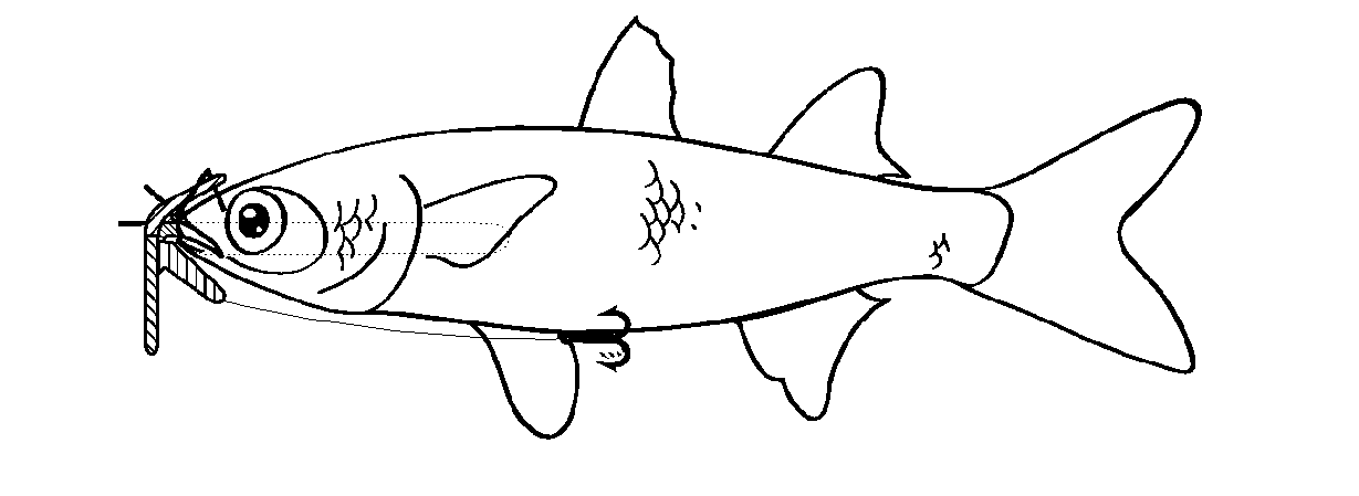
[0006]This arrangement allows the bait fish to be received and supported effectively on a simple and robust structure, but in such a way that it preserves the appearance of a live fish to predators.
[0008]The retaining means may comprise a first surface of a first, upper part for abutting an upper head portion of a bait fish and a second surface of a second, lower part for abutting a lower head portion of a bait fish. The upper part may comprise an upper bar adapted to resemble an upper profile of a head of a bait fish, and the lower part may comprise a lower bar adapted to resemble the lower profile of a head of a bait fish. This arrangement enables the fishing lure to preserve the overall appearance of the fish to any predator. The lower part may further comprise a bill to create a reciprocating lateral motion in use when a bait fish is mounted on the fishing lure and the mounted bait fish is pulled through the water. This provides the dynamic, as well as the static, appearance of a live fish to any predator.
[0009]The support rod, the upper part and the lower part may be fixed together in an intersection region to form the mounting body. This can provide a structure that is simple to produce and which has good structural strength. The mounting body may be formed as a unitary component, such as a moulded component. It may be made substantially of metal, a suitable metal being brass. The mounting body may have one or more eyelets for attaching a fishing line thereto. One or more of these eyelets may be provided in the intersection region. There may be a plurality of eyelets located on or adjacent to the upper part, such that one of said eyelets is located further from the lower part than another of said eyelets.
[0010]In embodiments, the lower bar may act as a counter balance weight, for example providing 15-20% of the weight of the fishing lure.
[0012]In embodiments, the support rod is weighted. It may provide 45-50% of the weight of the fishing lure. The support rod may be adapted to extend beyond the upper part and the lower part of the retaining means along a length of a bait fish, for example extending to approximately half the length of a preferred bait fish. With a support rod of this kind, the fishing lure gives good support to the bait fish, preserving life, without affecting its lifelike appearance.
[0017]The fixing means may comprise a locking pin rotatably mounted on the fishing lure and a penetrating member to penetrate the skull of a bait fish. The locking pin may be mounted substantially at the intersection point. The upper part or the lower part may be provided with an aperture, and wherein the penetrating member is adapted to pass through the aperture when fixing a bait fish to the mounting body. The locking pin may be formed of wire. This fixing means is straightforward, easy to manufacture, and effective to cooperate with other parts of the fishing lure to retain a bait fish effectively.

Problems solved by technology

While live bait can be used for this purpose, this creates numerous practical difficulties: it is necessary to obtain live bait, mount it appropriately, and check regularly that it is still alive.
In addition, live bait can only be trolled effectively at relatively low speeds.
Many difficulties in using live bait can be solved by using dead bait, but new difficulties arise.
While a number of fishing lures used for mounting dead bait have been developed, these are generally either complex to make, difficult to use, insufficiently lifelike or have some combination of these faults.

Method used


Image

  • Fishing Lures
  • Fishing Lures
  • Fishing Lures

Examples


first embodiment

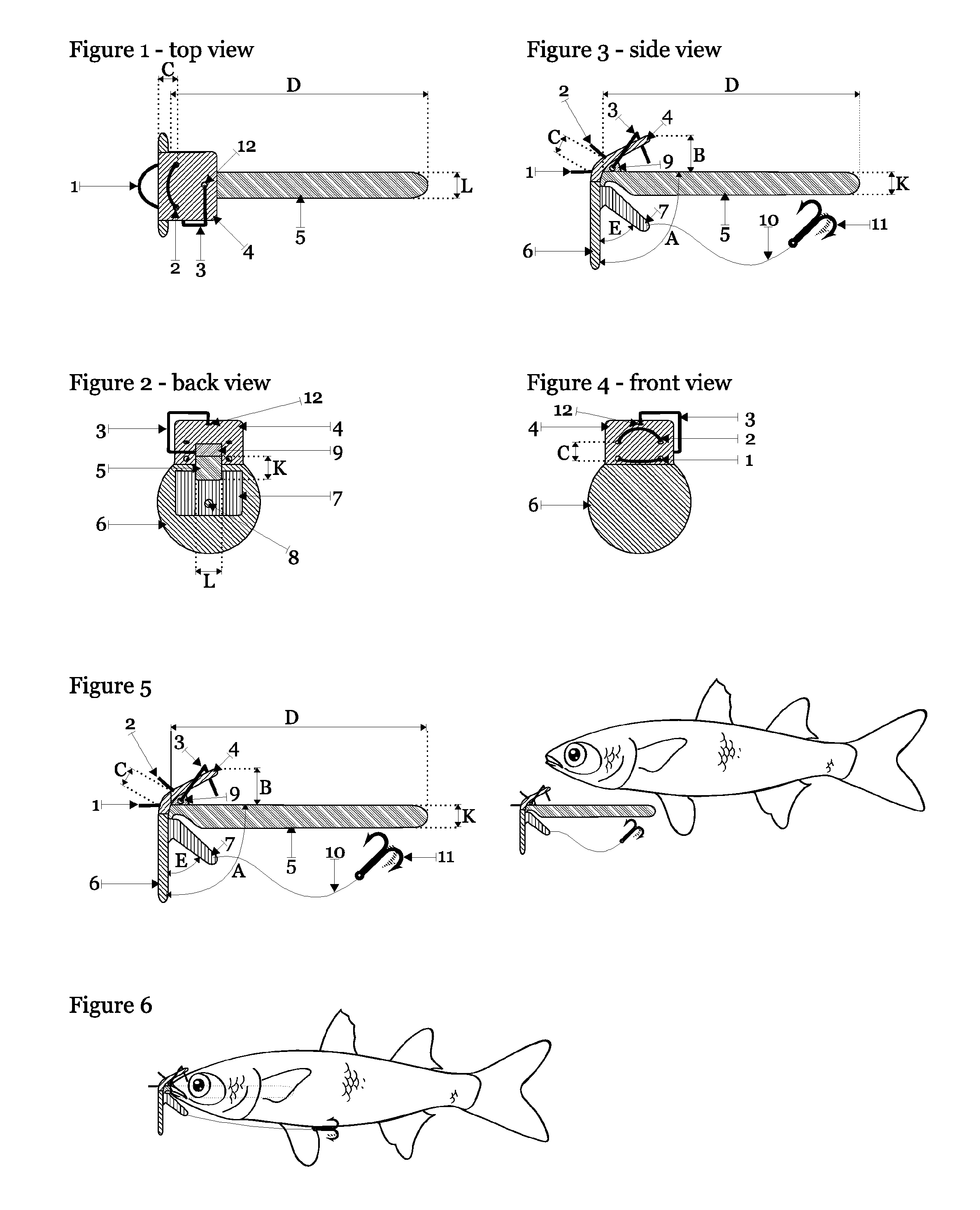
[0038]A first embodiment is described with reference to FIGS. 1 to 6.

[0039]FIGS. 1 to 4 show plan, rear elevation, side elevation and front elevations respectively of the first embodiment of a fishing lure. The fishing lure has a mounting body which comprises a first, upper, bar 4, a second, lower, bar 7, a rod 5 and a bill 6. The fishing lure is provided with a first eyelet 1 and a second eyelet 2, either of which may be attached to a fishing line for trolling the fishing lure from a boat. A hook 11 is mounted on a length of fishing line 10 attached to the lower bar 7 through an aperture 8. A fixing means in the form of a locking pin 3 is provided for fixing a dead bait fish on to the mounting body. The locking pin is rotatably mounted 9 on the mounting body to pass through an aperture 12 in the upper plate 4.

[0040]The elements of the mounting body are fixed together in use. In the arrangement shown, upper bar 4, lower bar 7, rod 5 and bill 6 are all moulded components. These are p...

third embodiment

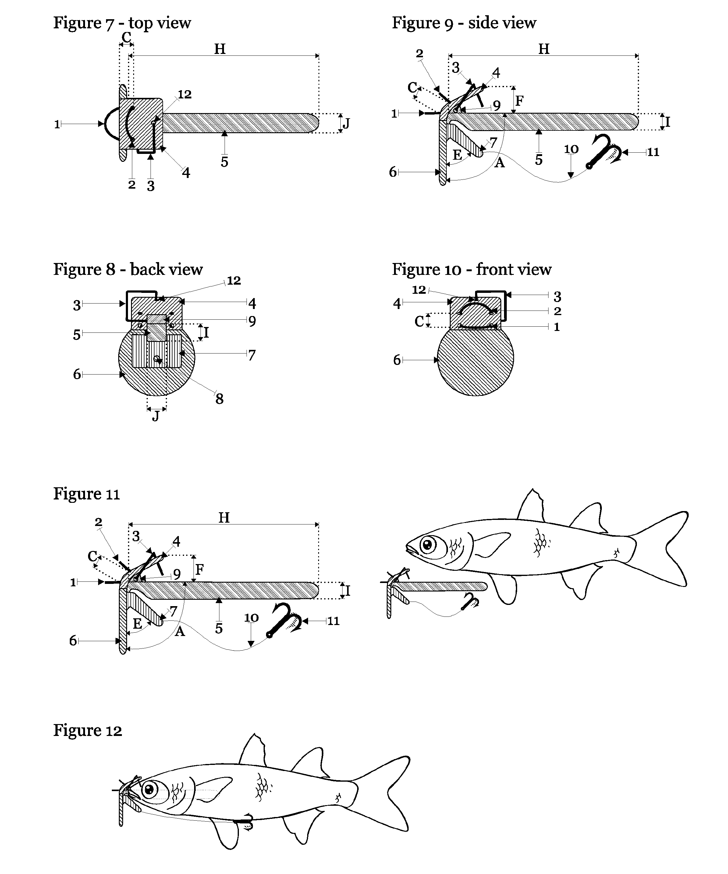
[0055]a fishing lure is shown in FIGS. 13 to 18. These Figures again generally resemble FIGS. 1 to 6 respectively, and the reference numerals again correspond to those used in these earlier Figures.

[0056]In this arrangement, the arrangement of the bill and the lower bar has been somewhat changed, while the other components of the fishing lure (such as the rod 5 and the upper bar 4) are unaffected, save only in their connection to the bill or the lower bar in the intersection region. In this arrangement the bill is displaced some distance along the lower bar, and it is strictly the lower bar, rather than the bill, which abuts the fixed end of the upper bar 4. The lower bar and the bill can in this arrangement be considered as a composite lower element 13 in FIGS. 13 to 18.

[0057]The lower bar extends vertically in the intersection region to abut at its fixed end the fixed end of the upper bar 4. As it extends away from the intersection region, the lower bar is bent at an angle to the ...


PUM


Abstract

A fishing lure for receiving a bait fish comprises a mounting body and a fixing means (3) for fixing a bait fish to the mounting body. The mounting body comprising a support rod (5) for inserting into the mouth of a bait fish to support the mounted bait fish and a retaining means (4, 7) disposed on the support rod (5) for abutting a head portion of the bait fish. The mounting body is adapted not to conceal, in use, eyes of a bait fish mounted on the mounting body.

Description

FIELD OF INVENTION[0001]The invention relates to a fishing lure and to a method of preparing bait using a fishing lure. In aspects, the invention relates to fishing lures suitable for mounting a dead bait fish for use in trolling, and to methods of constructing a baited trolling rig.BACKGROUND OF INVENTION[0002]Artificial lures are commonly used to catch fish, particularly in sport and recreational fishing. In order to catch fish which themselves prey upon other fish, it is desirable to use a lure which includes an appropriate bait fish. While live bait can be used for this purpose, this creates numerous practical difficulties: it is necessary to obtain live bait, mount it appropriately, and check regularly that it is still alive. In addition, live bait can only be trolled effectively at relatively low speeds.[0003]Many difficulties in using live bait can be solved by using dead bait, but new difficulties arise. To be an effective lure, the dead bait must sufficiently resemble live ...

Claims


Application Information

Patent Timeline
IPC IPC(8): A01K85/00A01K99/00
CPCA01K83/06
Inventor CAMILLERI, CLAYTON
Owner CAMILLERI CLAYTON
Learn More