Thermal Air Flow Sensor

a sensor and air flow technology, applied in the direction of volume/mass flow measurement, measurement devices, instruments, etc., can solve the problems of difficult dimension clearance control, inability to complete sealing, and liable variation of the mounting surface so as to avoid the breakage of the detecting element, improve the accuracy of measurement, and improve the effect of flow output characteristics

Active Publication Date: 2012-03-08
HITACHI ASTEMO LTD
View PDF11 Cites 16 Cited by
  • Summary
  • Abstract
  • Description
  • Claims
  • Application Information

AI Technical Summary

Benefits of technology

[0009]In order to attain the object, in a thermal air flow sensor according to the invention, a hollow formed in a detecting element is communicated with a circuit chamber in which driving circuit parts of the detecting element are mounted, or an exterior of an intake duct. Thereby, pressure in the hollow balances with pressure on the outside. Also, since the circuit chamber is provided to be isolated from a detection chamber (a passage chamber, through which air being a measuring object flows), in which a detecting part of the detecting element is arranged, air flowing in the passage chamber can be restrained from flowing into the hollow to have influence on flow output characteristics.
[0010]According to the invention, there is provided a thermal air flow sensor capable of avoiding breakage of a detecting element due to variation in temperature and pressure and realizing high-precision measurement of air flow.

Problems solved by technology

With the conventional, thermal air flow sensor, when a detecting element comprising the plate-shaped substrate formed with the hollow and the diaphragm is bonded to a support, a clearance between the rear surface of the detecting element and a detecting element mounting surface of the support is liable to vary widely in dimension and it is difficult to control the clearance in dimension.
When the whole periphery of the hollow is bonded by means of an adhesive to seal the inside of the hollow, however, there is caused a problem that complete sealing cannot be performed because variation in temperature and pressure causes air in the hollow (diaphragm rear surface) to expand in volume to result in breakage of the detecting element.

Method used


Image

  • Thermal Air Flow Sensor
  • Thermal Air Flow Sensor
  • Thermal Air Flow Sensor

Examples


embodiment 1

[0025]FIGS. 1 to 5 schematically show a thermal air flow sensor according to the invention.

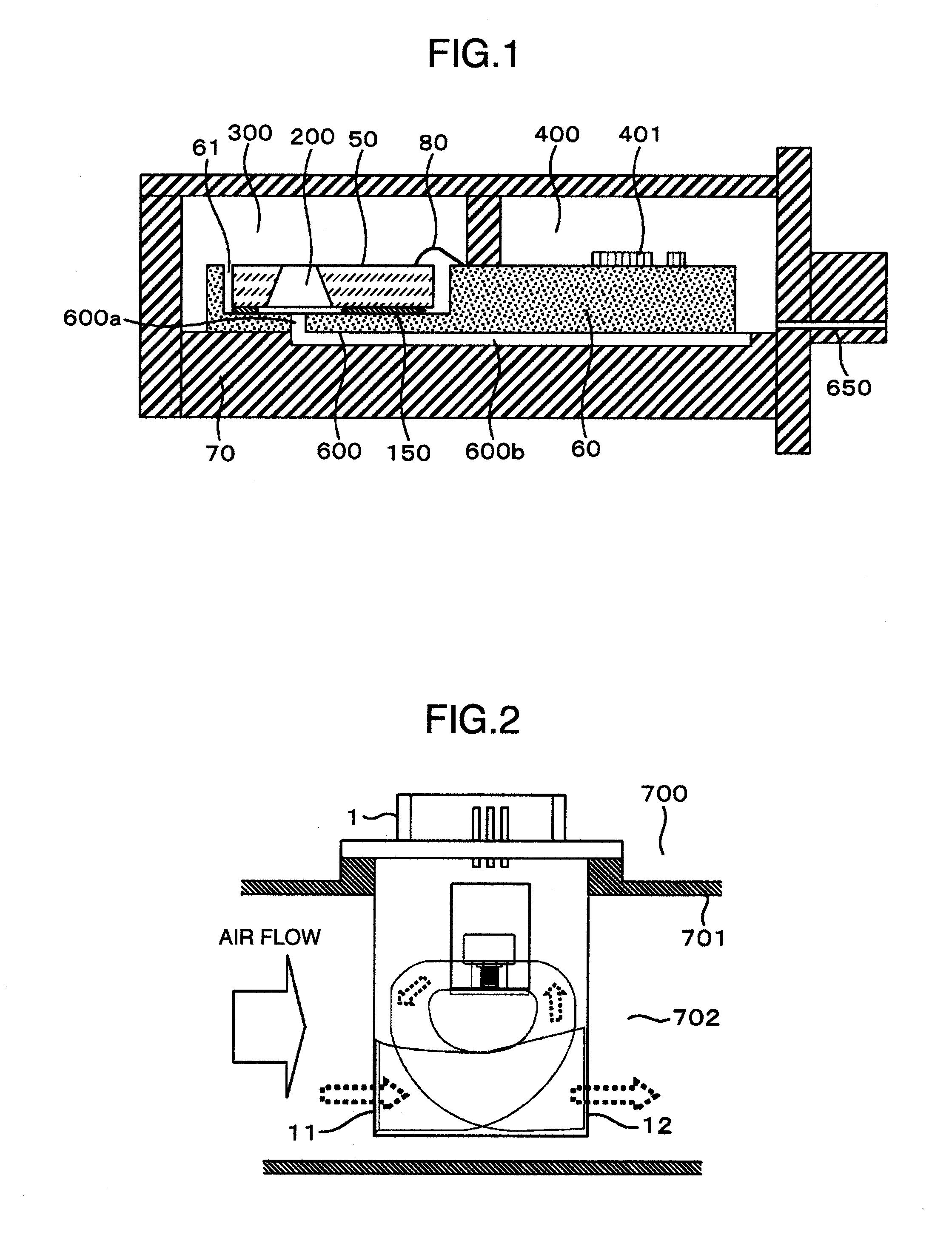
[0026]First, an environment, in which the thermal air flow sensor is mount will be described with reference to FIG. 2.

[0027]The thermal air flow sensor 1 is mounted to an intake duct 701 and air flowing in an intake duct interior 702 enters a passage from an upstream side opening 11 of the thermal air flow sensor 1, goes through the passage, and goes out of a downstream side opening 12.

[0028]Also, since an intake duct exterior 700 is completely isolated from the intake duct interior 702, the intake duct exterior 700 is put in a windless state even when air flows in the intake duct interior 702.

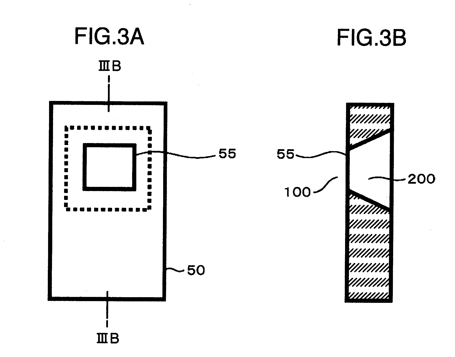
[0029]Subsequently, shape of a detecting element will be described with reference to FIG. 3.

[0030]In general, the detecting element 50 is rectangular-shape. A detecting part of the detecting element 50 comprises a thin film region called a diaphragm 55, and the diaphragm 55 is arranged in a passage chamb...

first embodiment

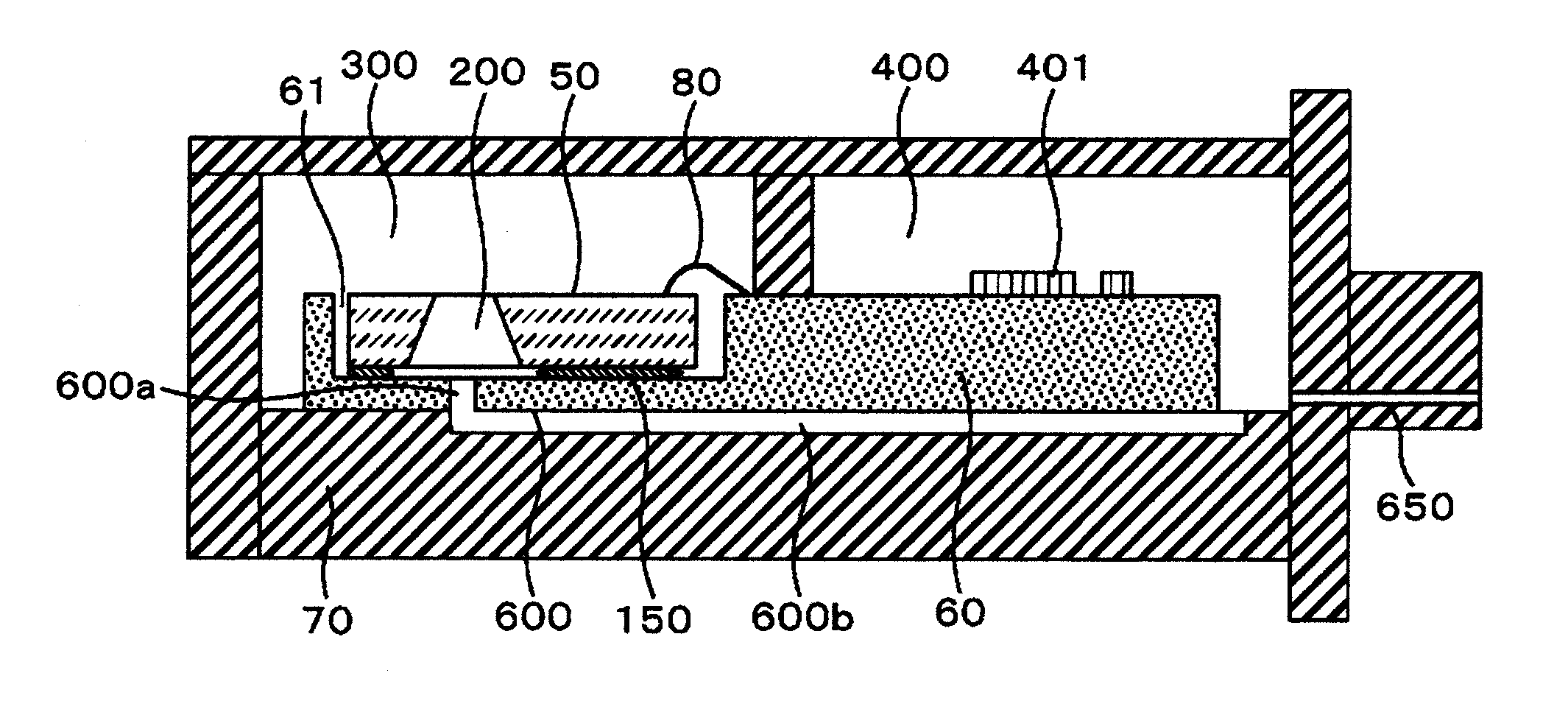
[0032]Subsequently, a first embodiment of a thermal air flow sensor according to the invention will be described with reference to FIG. 1.

[0033]In the present embodiment, the detecting element 50 is mounted on a LTCC (Low Temperature Co-Fired Ceramic) laminated substrate 60 (referred hereinafter to as ceramic substrate). A dent called a cavity 61 is provided in the ceramic substrate 60 so as to enable receiving the detecting element 50.

[0034]The detecting element 50 and the ceramic substrate 60 are connected electrically to each other by an Au wire 80.

[0035]All four sides of the detecting element 50 are bonded in the cavity 61 by means of an adhesive 150 as shown in FIGS. 4A and 4C. At this time, the use of the adhesive forms a clearance in the order of 1 μm˜100 μm between the rear surface of the detecting element 50 and a bottom surface of the cavity 61.

[0036]In this case, in order to isolate the hollow 200 of the detecting element 50 from the passage chamber 300, an application pa...

second embodiment

[0044]FIG. 6 schematically shows a second embodiment of a thermal air flow sensor according to the invention. The second embodiment is the same in fundamental constitution as that of the first embodiment. In the second embodiment, a ventilation hole 600 for communication between a hollow 200 and a circuit chamber 400 is formed in a ceramic substrate 60.

[0045]While the second embodiment adopts a LTCC substrate as a ceramic substrate, on which a detecting element 50 is mounted, in the same manner as in the first embodiment, another ceramic substrate, a print board, or a metallic substrate may be adopted.

[0046]By forming the ventilation hole 600 in a single constituent member, assembling of respective constituent members is increased in degree of freedom of positional tolerance and it is possible to eliminate possibility that the ventilation hole 600 is interrupted at a joint face due to dislocation.


PUM


Abstract

In a thermal air flow sensor according to the invention, a hollow formed in a detecting element is communicated with a circuit chamber, in which driving circuit parts of the detecting element are mounted, or an intake duct exterior. Thereby, pressure in the hollow balances with pressure on the outside. Also, since the circuit chamber is provided to be isolated from a detection chamber, in which a detecting part of the detecting element is arranged, that is, a passage chamber, through which air being a measuring object flows, air flowing in the passage chamber can be restrained from flowing into the hollow to have an influence on flow output characteristics.

Description

BACKGROUND OF THE INVENTION[0001]The present invention relates to a sensor for measuring flow rate of fluid, and more particular, to a thermal air flow sensor.[0002]As an air flow sensor provided in an intake manifold of an internal combustion engine in automobiles, etc. to measure an intake air quantity, a thermal air flow sensor has become the mainstream because of its ability of direct detection of a mass air quantity.[0003]Recently, attention has been paid to air flow sensors manufactured by means of the semiconductor micromachining technology because of high speed responsibility and capability of detection of reverse flow making use of a high speed in responsibility.[0004]However, it is known that thermal air flow sensors with the use of a semiconductor substrate are varied in flow output characteristics due to invasion of dirt substances, such as oil, dust, etc., and moisture onto a rear surface of a detecting element. JP-A-2003-270016 discloses a thermal air flow sensor, in w...

Claims


Application Information

Patent Timeline
Patent Type & Authority Applications(United States)
IPC IPC(8): G01F1/68
CPCG01F1/6845G01F5/00G01F1/692G01F15/10G01F15/105G01F1/6842
Inventor DOI, RYOSUKEHANZAWA, KEIJI
Owner HITACHI ASTEMO LTD
Why Eureka
Try Eureka