Tank unit and liquid ejecting system having tank unit

a tank unit and liquid ejecting technology, which is applied in the direction of metal-working equipment, printing, writing implements, etc., can solve the problems of printer problems, increased production costs of ink tanks, and complicated production processes of ink tanks, so as to achieve easy assembly and integration, the effect of film being easily broken and being easily disposed o

Active Publication Date: 2012-03-08
SEIKO EPSON CORP
View PDF1 Cites 54 Cited by
  • Summary
  • Abstract
  • Description
  • Claims
  • Application Information

AI Technical Summary

Benefits of technology

[0011]In many embodiments, at least one of the facing walls defines a concave-shaped receptacle open to a side of the main body opposite to the liquid accommodating chamber. And two or more of the liquid accommodating chambers are disposed such that the film covered side opening of at least one of the liquid accommodating chambers is disposed within the concave-shaped receptacle of the adjacent one of the liquid accommodating chambers. Accordingly, since the film covered side opening is disposed within the concave-shaped receptacle of the adjacent one of the liquid accommodating chambers, a possibility that the film may be broken can be further reduced. Further, the liquid accommodating containers adjacent to each other can be easily fitted to and integrated with each other by making one side face of one liquid accommodating container enter the concave portion of the facing wall of the other adjacent liquid accommodating container.
[0012]In many embodiments, each of the liquid accommodating chambers further includes at least one fitting unit. Each of the fitting units is configured for removable coupling to one of the fitting units of an adjacent one of the liquid accommodating containers. Each of the fitting units can include a projection portion and a hole portion into which the projection portion of a fitting unit of an adjacent one of the liquid accommodating containers is fitted. Accordingly, two or more of the liquid accommodating containers can be easily assembled and integrated and a possibility that the integrated liquid accommodating containers may come apart can also be reduced.
[0013]In many embodiments, the tank unit further includes a cover member. The cover member covers the film of one of the liquid accommodating containers disposed at an end of the row. Accordingly, a possibility that the film of the exposed liquid accommodating container may be broken can be reduced.
[0014]In many embodiments, each of the liquid accommodating chambers includes a liquid injection port through which liquid can be injected into the liquid accommodating chamber and a detachably mounted plug member configured to block the liquid injection port. At least one of the plug members is connected to a plug member of an adjacent one of the liquid accommodating containers by a connection member. Accordingly, even in a case where the plug member (also referred to as a “target plug member”) is detached from the liquid injection port when injecting liquid into one liquid accommodating container, the target plug member remains connected to the plug member (also referred to as an “adjacent plug member”) of the other adjacent liquid accommodating container. Here, since the adjacent plug member remains mounted on the liquid injection port, even if the target plug member is detached, the target plug member is located in the vicinity of the adjacent plug member. Accordingly, a possibility that a user may lose the detached plug member can be reduced.
[0015]In another aspect, a liquid ejecting system is provided. The liquid ejecting system can include any tank unit as set forth herein, a liquid ejecting apparatus that includes a head configured to eject liquid onto a target, and a flow tube that connects the tank unit and the liquid ejecting apparatus. The flow tube is configured to transfer liquid from the tank unit to the liquid ejecting apparatus. Accordingly, a liquid ejecting system can be provided that receives a supply of liquid from the tank unit and then ejects the liquid onto a target, in which a possibility that impurities may be mixed with liquid in the tank unit is reduced.
[0016]In many embodiments, the liquid ejecting apparatus includes a printer and the tank unit accommodates one or more inks. Accordingly, a liquid ejecting system can be provided that receives a supply of ink from the tank unit and then ejects the ink onto a target, in which a possibility that impurities may be mixed with ink accommodated in the tank unit is reduced.

Problems solved by technology

However, in the case of manufacturing a tank unit by combining a plurality of ink tanks manufactured by using vibration welding, there is a case where various problems arise.
In this case, ink with the shaving dregs mixed therein is supplied from a tank unit to a printer, causing generation of problems for the printer.
Further, in the case of manufacturing an ink tank by using vibration welding, a device for vibration welding needs to be used, so that there is a case where the production costs of the ink tank increase or the production process of the ink tank is complicated.
Such problems are not limited to the tank unit which includes the ink tanks and are problems common to a tank unit which is provided with liquid accommodating containers and is for supplying liquid from the outside of a liquid ejecting apparatus to the liquid ejecting apparatus.

Method used


Image

  • Tank unit and liquid ejecting system having tank unit
  • Tank unit and liquid ejecting system having tank unit
  • Tank unit and liquid ejecting system having tank unit

Examples


Embodiment Construction

[0030]In the following description, various embodiments of the present invention will be described. For purposes of explanation, specific configurations and details are set forth in order to provide a thorough understanding of the embodiments. However, it will also be apparent to one skilled in the art that the present invention may be practiced without the specific details. Furthermore, well-known features may be omitted or simplified in order not to obscure the embodiment being described.

Liquid Ejecting System

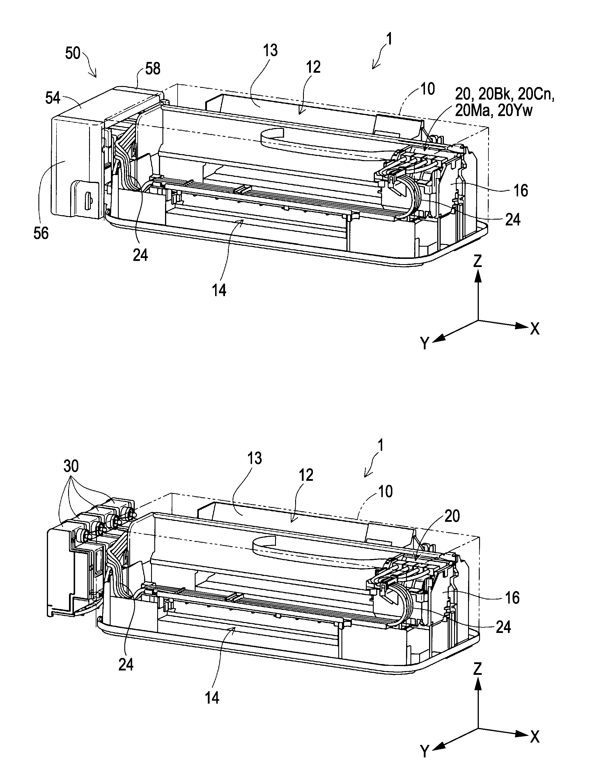
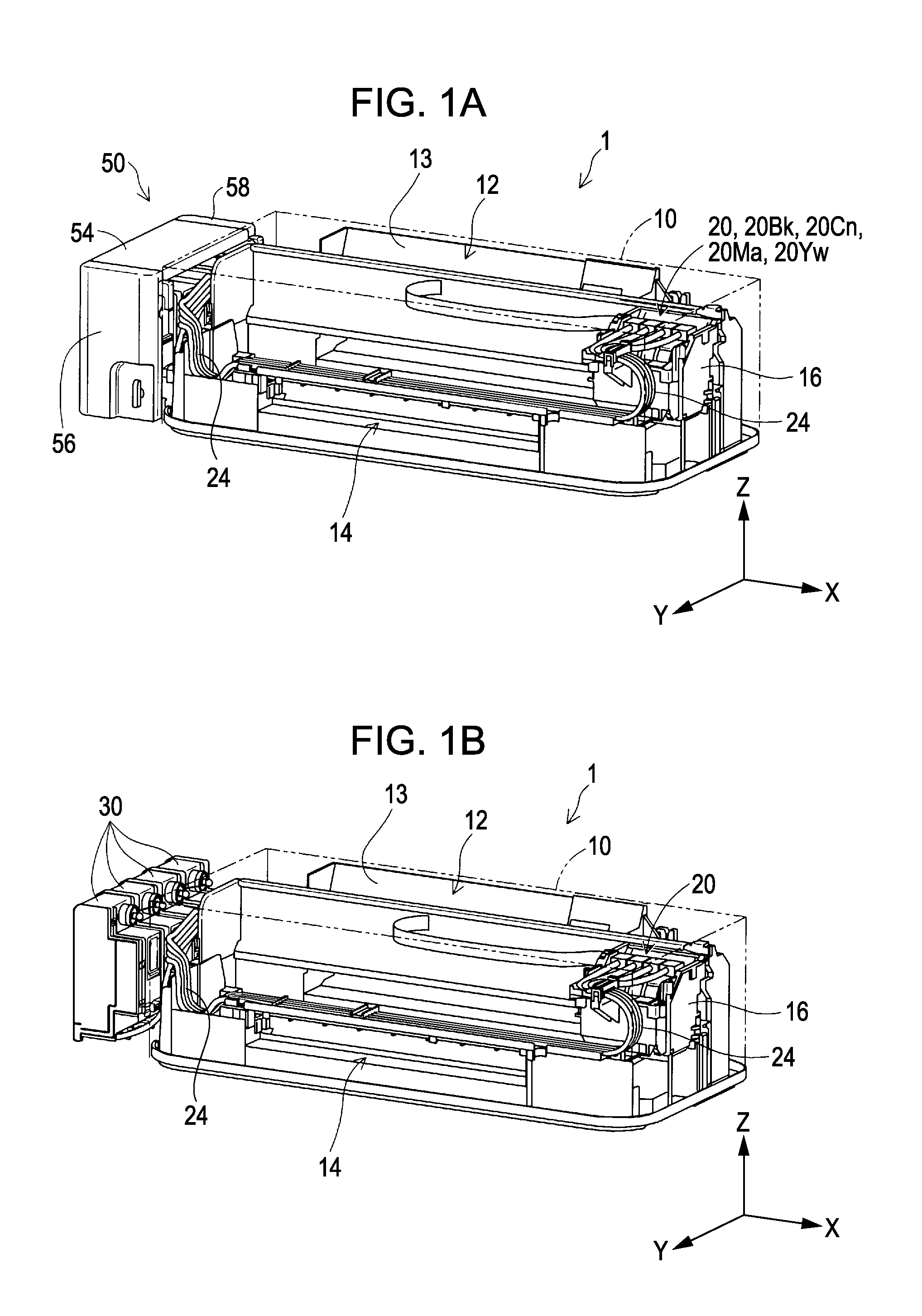
[0031]Referring now to the drawings, in which like reference numerals represent like parts throughout the several views, FIGS. 1A and 1B are diagrams for describing a liquid ejecting system 1 of an example. FIG. 1A is a first exterior perspective view of the liquid ejecting system 1. FIG. 1B is a second exterior perspective view of the liquid ejecting system 1 and is a diagram illustrating liquid accommodating containers 30 of the example of the invention. In addition, in FIG...


PUM

PropertyMeasurementUnit
liquidaaaaaaaaaa
concave shapeaaaaaaaaaa
colorsaaaaaaaaaa

Abstract

A tank unit includes two or more liquid accommodating containers disposed in a row. Each of the liquid accommodating containers includes a main body having a concave shape defining a side opening and a film that blocks the side opening. The main body and the film at least partially define a liquid accommodating chamber for accommodating a liquid. The main body includes a facing wall that faces the film across the liquid accommodating chamber and has a wall larger than the side opening. The liquid accommodating containers are disposed such that the film of at least one of the liquid accommodating containers is covered by the facing wall of an adjacent one of the liquid accommodating containers.

Description

[0001]This application claims priority to Japanese Patent Application No. 2010-197269, filed Sep. 3, 2010, the entirety of which is incorporated by reference herein.BACKGROUND[0002]1. Technical Field[0003]The present invention relates to a tank unit that includes two or more liquid accommodating containers and a liquid ejecting system that includes the tank unit.[0004]2. Related Art[0005]A printer, which is one example of a liquid ejecting apparatus, performs printing by discharging ink from a recording head onto a recording target (for example, printing paper). A known technique of supplying ink to a recording head includes supplying ink from a tank unit disposed external to the recording head through a tube (for example, JP-A-2005-219483). The tank unit can include two or more ink tanks (liquid accommodating containers), which accommodate ink.[0006]An ink tank of the tank unit needs to have an internal space to accommodate ink. Here, there is a case where an ink tank having a spac...

Claims


Application Information

Patent Timeline
Patent Type & Authority Applications(United States)
IPC IPC(8): B41J2/135B23P17/00
CPCB41J2/175Y10T29/49401B41J2/17553B41J2/17513B41J2/17503B41J2/185
Inventor ISHIZAWA, TAKUSHIMIZU, YOSHIAKITAKAHASHI, MASARU
Owner SEIKO EPSON CORP
Why Eureka
Try Eureka