Laser scanner or laser tracker having a projector

a laser scanner and projector technology, applied in the direction of measurement devices, active open surveying means, instruments, etc., can solve the problem of distance information to be los

Active Publication Date: 2012-03-08
FARO TECH INC
View PDF6 Cites 105 Cited by
  • Summary
  • Abstract
  • Description
  • Claims
  • Application Information

AI Technical Summary

Problems solved by technology

If the beam is broken during the measurement, the number of counts...

Method used


Image

  • Laser scanner or laser tracker having a projector
  • Laser scanner or laser tracker having a projector
  • Laser scanner or laser tracker having a projector

Examples


Embodiment Construction

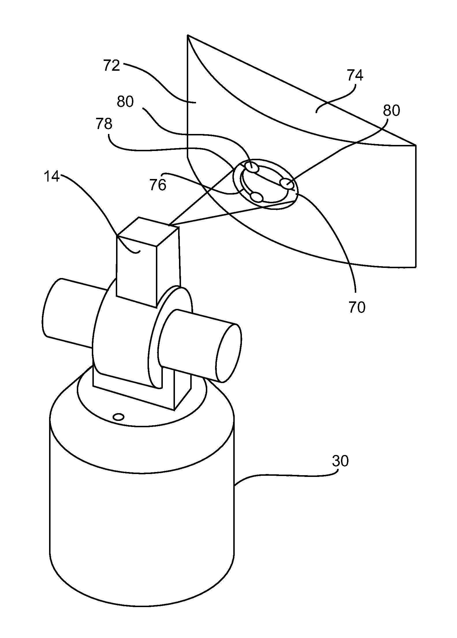
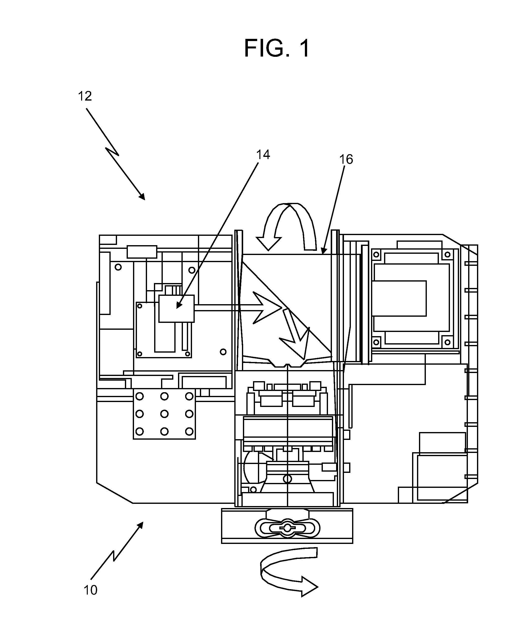
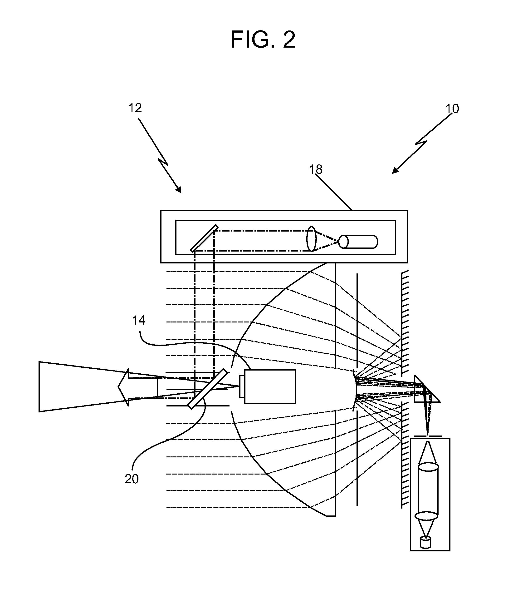
[0028]Referring to FIG. 1, in accordance with embodiments of the present invention, there illustrated is a rotating scanning head portion 10 of a laser scanner 12 having a commercially available, relatively small or “miniature,”“ultraminiature,” or “pico” projector 14 integrated directly within the optical components (“optics”) located within the scanner head 10. The projector 14 may contain some amount of processing capability, as is known. The projector 14 may be connected with, or in communication with, a computer or processor of the laser scanner 12, where the computer or processor may be integral with the scanner 12 (e.g., located within the scanner head 10) or may be separate therefrom (e.g., a laptop computer). The scanner head 10 is typically mounted to a supporting tripod (not shown), which sits on the ground or other surface during laser scanner use. As described in more detail with respect to FIG. 2, the projector 14 sends various images, data or other information through...


PUM


Abstract

A laser scanner or a laser tracker includes a light source that emits a light beam within an environment, and a data capture component that captures the light beam reflected back to the laser scanner or tracker from the environment. The laser scanner or tracker also includes a projector integrated within a body of the laser scanner or tracker or mounted to the body of the laser scanner or tracker at a predetermined location, the projector being operable to project visible information onto an object located within the environment, the projected visible information being indicative of images, data or information, the projected visible information being at least one of design intent information, information acquired by the laser scanner or tracker, or guidance to an operator.

Description

CROSS-REFERENCE TO RELATED APPLICATIONS[0001]This application claims priority to U.S. Provisional Application No. 61 / 380,869, filed on Sep. 8, 2010; to U.S. Non-Provisional application Ser. No. 13 / 006,507, filed on Jan. 14, 2011; to U.S. Non-Provisional application Ser. No. 13 / 006,468, filed on Jan. 14, 2011; and to U.S. Non-Provisional application Ser. No. 13 / 006,524, filed on Jan. 14, 2011; the entire contents of each which are incorporated herein by reference.FIELD OF THE INVENTION[0002]The present invention relates to coordinate measurement devices, for example, laser scanners, laser trackers, and total stations, and more particularly to laser scanners and laser trackers having one or more relatively small projectors integrated therewith or added thereto by, e.g., mounting thereon, for projecting visual information in the form of images and / or data (e.g., CAD data or scanned point cloud data) onto various surfaces. The projected visual information may, for example, be of a type ...

Claims


Application Information

Patent Timeline
IPC IPC(8): G01B11/24G03B21/14G01S17/89
CPCG01C15/002G01S17/89G01S7/51G01S7/4817
Inventor BRIGGS, CLARK H.
Owner FARO TECH INC
Why Eureka
Try Eureka