Line-projection apparatus for arrays of diode-laser bar stacks

a technology of diode-laser bar and array, which is applied in the field of optical equipment, can solve the problems of not being able to offer 100-bar stacks at economical cost, the practicability limit of how many can be stacked in a module, and the inability to commercially offer modules with 100-bar fast-axis stacked bars

Active Publication Date: 2012-03-08
COHERENT INC
View PDF1 Cites 133 Cited by
  • Summary
  • Abstract
  • Description
  • Claims
  • Application Information

AI Technical Summary

Problems solved by technology

However, each diode-laser bar must be individually cooled, and there is a practical limit to how many can be stacked in a module, dependent, inter alia, on selecting sufficient bars from a batch with adequate specif...

Method used


Image

  • Line-projection apparatus for arrays of diode-laser bar stacks
  • Line-projection apparatus for arrays of diode-laser bar stacks
  • Line-projection apparatus for arrays of diode-laser bar stacks

Examples


Embodiment Construction

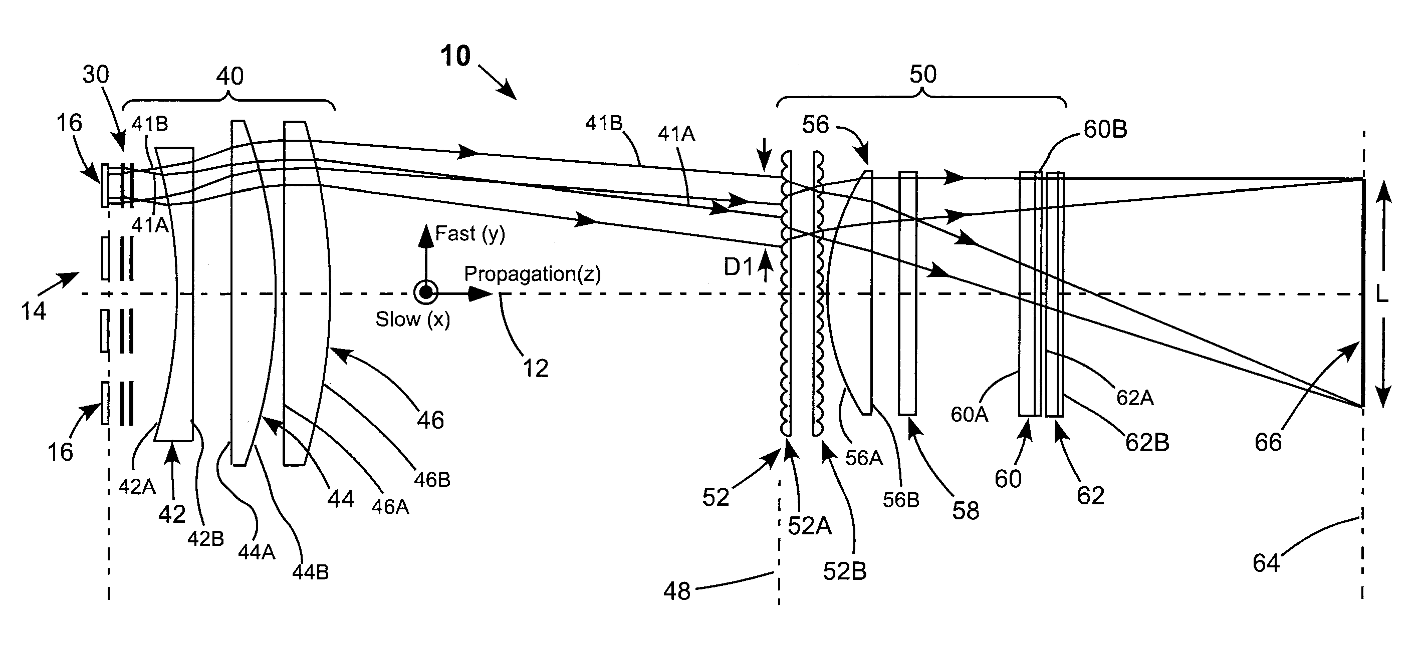
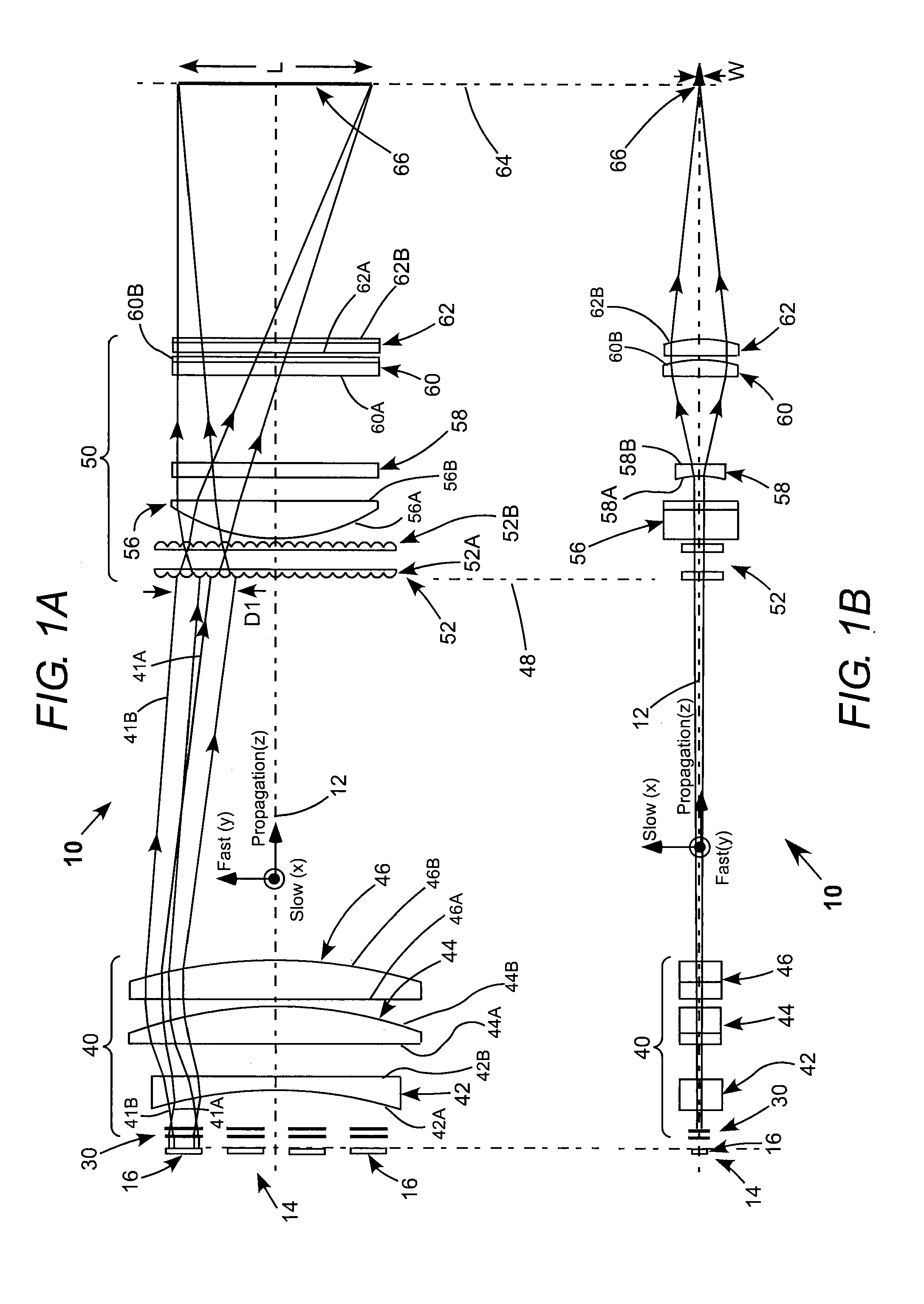
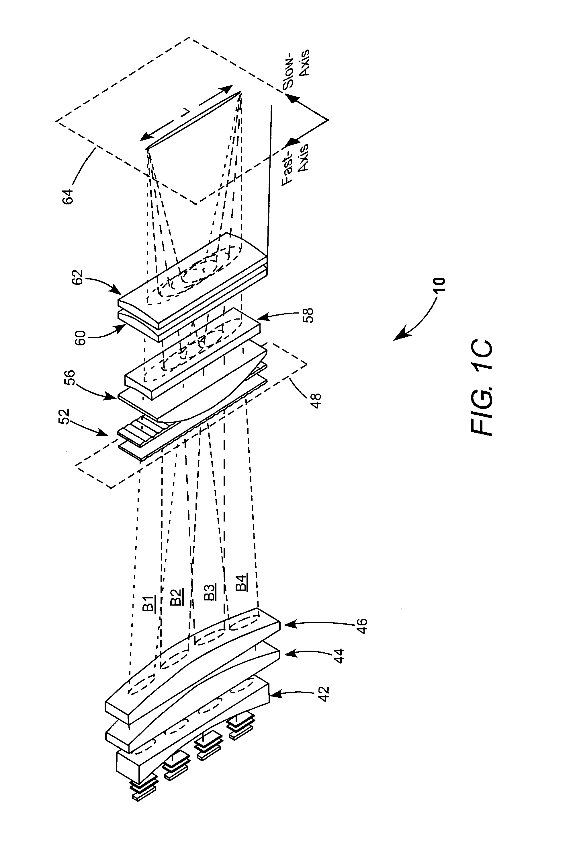
[0022]Referring now to the drawings, wherein like components are designated by like reference numerals, FIG. 1A and FIG. 1B are respectively fast-axis and slow-axis views schematically illustrating one preferred embodiment 10 of line-illuminating apparatus in accordance with the present invention. Apparatus 10 has a system axis 12. FIG. 1C is a three-dimensional view schematically illustrating further details of the apparatus of FIGS. 1A and 1B.

[0023]Apparatus 10 has a light-source 14 including four fast-axis diode-laser bar-stack modules 16 aligned one above the other in the fast-axis-direction of the stacks. In the description of apparatus 10 set forth below the apparatus is also described, for convenience of description, as having a fast-axis and a slow-axis corresponding to the same axes of the diode-laser bars. These can also be arbitrarily designated respectively as the y-axis and the x-axis, corresponding to the tangential and sagittal axes of optics the apparatus. The propag...


PUM


Abstract

In optical apparatus for illuminating a mask-plane with a line of light, a light source includes four fast-axis stacks of laser diode bars. One optical arrangement collects light beams from all of the diode-laser bar stacks, homogenizes and expands the beams in the fast-axis direction of the diode-laser bar stacks and partially overlaps the homogenized and expanded beams in the fast-axis direction. Another optical arrangement homogenizes the sum of the partially overlapped beams and images the sum of the beams as a line of light having a length in the fast-axis-direction and a width in the slow-axis direction.

Description

PRIORITY CLAIM[0001]This application claims priority to prior Provisional Application Ser. No. 61 / 380,503, filed Sep. 7, 2010, the disclosure of which is incorporated herein by reference.TECHNICAL FIELD OF THE INVENTION[0002]The present invention relates in general to optical apparatus for projecting the output of one or more lasers into a line of light. The invention relates in particular to apparatus for forming very uniform line of light from the output of group of diode-laser barsDISCUSSION OF BACKGROUND ART[0003]There are several applications for laser radiation projected to form a line of light on a target. Early versions of such line-projection apparatus for diode-lasers were found in bar-code readers and the like. Here, however, uniformity of illumination along the line was at most a secondary consideration.[0004]Later versions of diode-laser line projection apparatus were developed for spatial light modulators (SLMs) in laser printers, image projectors, and the like. Here, ...

Claims


Application Information

Patent Timeline
IPC IPC(8): F21V5/00
CPCG02B27/0961G02B27/0966H01S5/02264G02B19/0014H01S5/4025H01S5/405G02B19/0057H01S5/4012H01S5/02365
Inventor KUCHIBHOTLA, SIVARAMA KRISHNA
Owner COHERENT INC
Why Eureka
Try Eureka