Method and apparatus for passive radio frequency indentification (RFID) reader digital demodulation for manchester subcarrier signal

a passive radio frequency indentification and digital demodulation technology, applied in the direction of instruments, dc level restoring means or bias distorting correction, baseband system details, etc., can solve the problem of difficult extraction of useful tag information, and achieve the effect of accurate detection of tag information

Inactive Publication Date: 2012-03-08
ELECTRONICS & TELECOMM RES INST
View PDF5 Cites 20 Cited by
  • Summary
  • Abstract
  • Description
  • Claims
  • Application Information

AI Technical Summary

Benefits of technology

[0033]According to embodiments of the present invention, in a passive radio frequency identification (RFID) environment where a direct current (DC) offset noise may exist in a Manchester subcarrier signal containing DC components in a frequency r...

Problems solved by technology

Accordingly, extract useful ...

Method used


Image

  • Method and apparatus for passive radio frequency indentification (RFID) reader digital demodulation for manchester subcarrier signal
  • Method and apparatus for passive radio frequency indentification (RFID) reader digital demodulation for manchester subcarrier signal
  • Method and apparatus for passive radio frequency indentification (RFID) reader digital demodulation for manchester subcarrier signal

Examples


Embodiment Construction

[0058]Reference will now be made in detail to exemplary embodiments of the present invention, examples of which are illustrated in the accompanying drawings, wherein like reference numerals refer to the like elements throughout. Exemplary embodiments are described below to explain the present invention by referring to the figures.

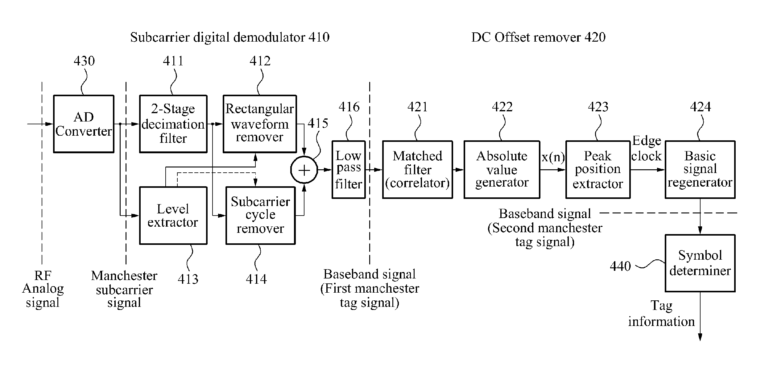
[0059]FIG. 4 is a block diagram illustrating a structure of a passive radio frequency identification (RFID) reader digital demodulation apparatus 400 with respect to a Manchester subcarrier signal, according to an embodiment of the present invention.

[0060]Referring to FIG. 4, the passive RFID reader digital demodulation apparatus 400, hereinafter, referred to as ‘RFID reader digital demodulation apparatus’, includes an RF / analog amplitude shift keying (ASK) demodulator (not shown), a subcarrier digital demodulator 410, a direct current (DC) offset remover 420, an analog / digital (A / D) converter 430, and a symbol determiner 440.

[0061]The subcarrier digital de...


PUM


Abstract

An apparatus and method for passive radio frequency identification (RFID) reader digital demodulation with respect to a Manchester subcarrier signal are disclosed. In a passive RFID environment where the Manchester subcarrier signal contains DC components in a frequency region, even when a tag signal containing the DC offset noise is input to a baseband, demodulation may be efficiently performed while the DC offset noise is removed. Therefore, accurate detection of tag information from the tag signal may be achieved.

Description

CROSS-REFERENCE TO RELATED APPLICATION[0001]This application claims the benefit of Korean Patent Application No. 10-2010-0087830, filed on Sep. 8, 2010, in the Korean Intellectual Property Office, the disclosure of which is incorporated herein by reference.BACKGROUND[0002]1. Field of the Invention[0003]The present invention relates to a method of effectively removing, from a tag signal distorted by the DC offset noise, a direct current (DC) offset noise generated from a baseband of a receiving end of a passive radio frequency identification (RFID) demodulation apparatus.[0004]2. Description of the Related Art[0005]Generally, according to a radio-frequency identification (RFID) scheme, information is extracted from or written on an RFID tag which contains specific ID information, without physical contact using a wireless frequency, thereby enabling recognition, tracking, and management of an object, an animal, a person, and the like attached with the RFID tag.[0006]An RFID system usi...

Claims


Application Information

Patent Timeline
IPC IPC(8): H04L25/06
CPCG06K7/10009H04L25/4904H04L25/06
Inventor BAE, JI HOONLEE, DONG HAN
Owner ELECTRONICS & TELECOMM RES INST
Why Eureka
Try Eureka