Development device, process cartridge, and image forming apparatus including same

a development device and process cartridge technology, applied in electrographic process devices, instruments, optics, etc., can solve problems such as affecting image development, affecting image quality and affecting image developmen

Active Publication Date: 2012-03-08
RICOH KK
View PDF23 Cites 7 Cited by
  • Summary
  • Abstract
  • Description
  • Claims
  • Application Information

AI Technical Summary

Problems solved by technology

Thus, the pitch of grooves causes unevenness in the image density, degrading the image quality.
Small-diameter toner having a lower melting point is less durable against stress, and changes in the properties thereof can affect image development.
However, in unidirectional circulation type development devices, the velocity at which the developer is transported should be increased, and thus enhanced transport ability (i.e., rotational frequency) is required, resulting in increases in size of the development device as well as increases in the stress on the developer.
However, the cost is increased when stainless steel is used, and strength is not sufficient when aluminum is used.

Method used


Image

  • Development device, process cartridge, and image forming apparatus including same
  • Development device, process cartridge, and image forming apparatus including same
  • Development device, process cartridge, and image forming apparatus including same

Examples


first embodiment

[0069]A first embodiment is described below with reference to FIGS. 1 through 8.

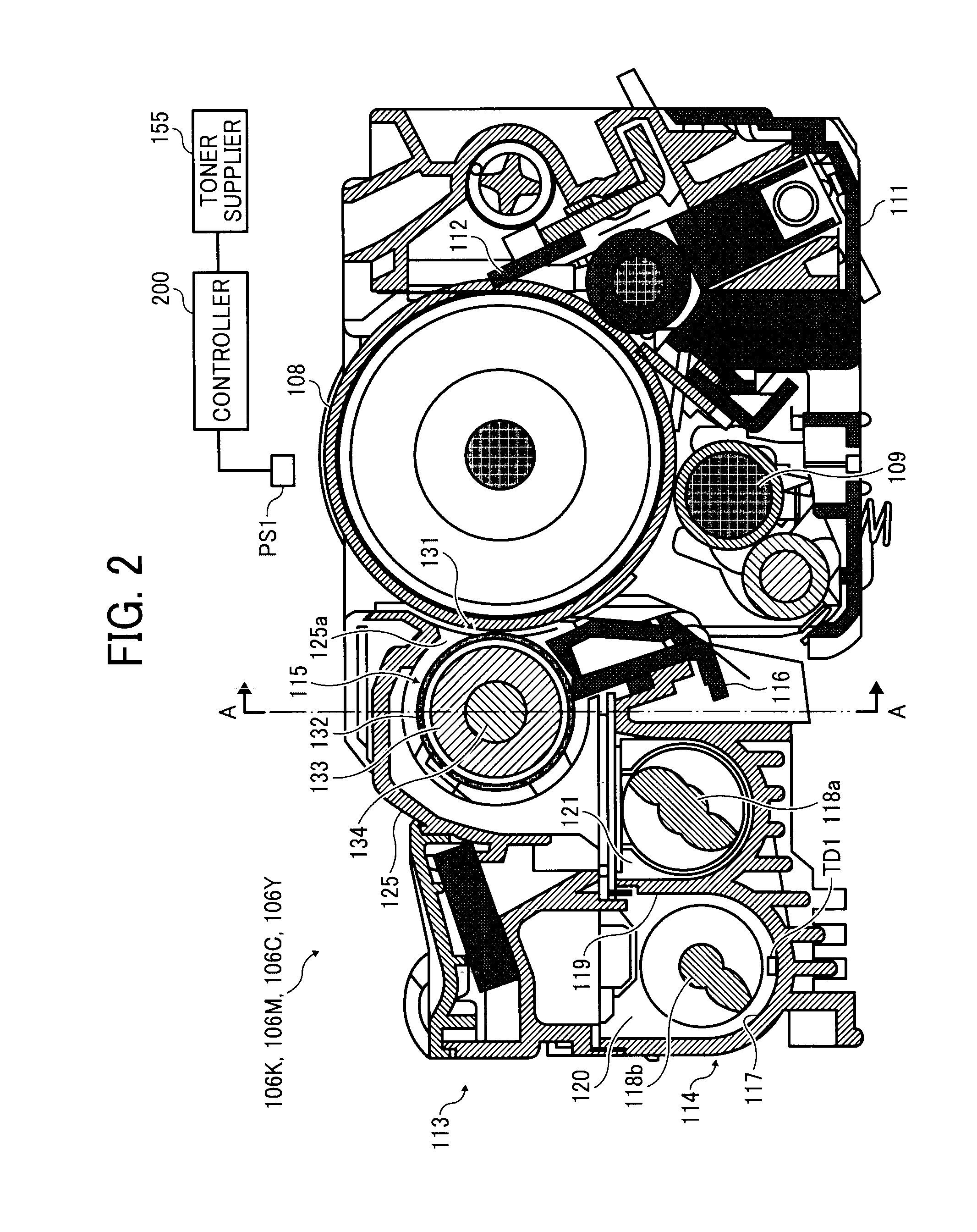
[0070]Initially, a configuration of an image forming apparatus according to the present embodiment, which may be a multicolor copier, for example, is described below.

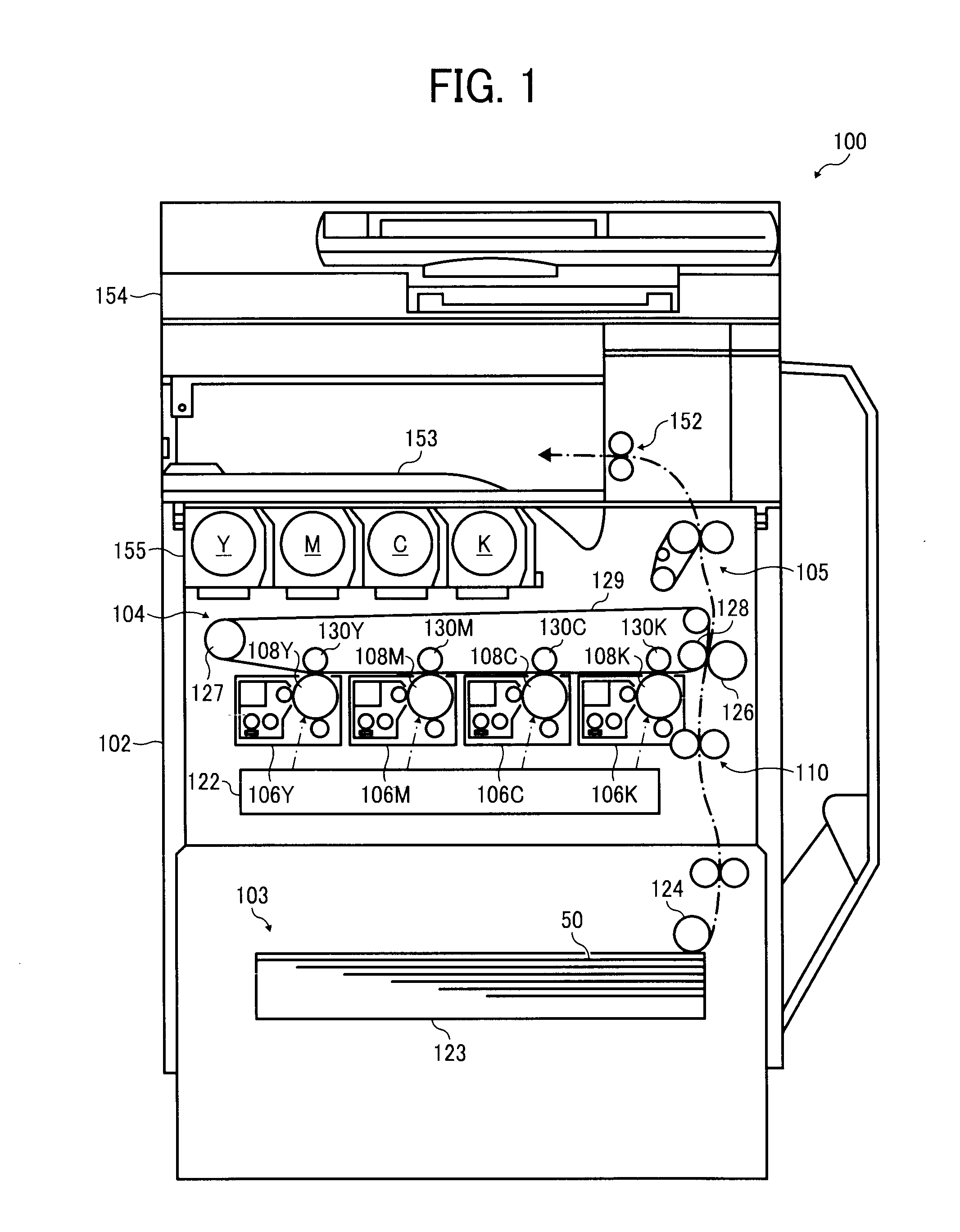
[0071]Referring to FIG. 1, an image forming apparatus 100 is a tandem image forming apparatus that uses an intermediate transfer belt 129 and forms a multicolor image on a recording sheet 50 by superimposing yellow (Y), magenta (M), cyan (C), and black (K) single-color images one on another. It is to be noted that that the suffixes Y, M, C, and K attached to the end of each reference numeral indicate only that components indicated thereby are used for forming yellow, magenta, cyan, and black images, respectively, and hereinafter may be omitted when color discrimination is not necessary.

[0072]Referring to FIG. 1, the image forming apparatus 100 includes a main body 102, a sheet feeder 103, a pair of registration rollers 110, an intermediate t...

second embodiment

[0136]A second embodiment is described below with reference to FIG. 9.

[0137]It is to be noted that components similar to those of the above-described embodiment are given identical or similar reference characters, and thus descriptions thereof omitted.

[0138]As shown in FIG. 9, in the present embodiment, the long axis of each recess 139 is curved so that its center portion is recessed upstream in the rotational direction Y1 of the development sleeve 132, that is, the center portion projects in the direction opposite the rotational direction Y1 of the development sleeve 132.

[0139]The recess 139 thus curved in the rotational direction Y1 of the development sleeve 132 can scoop the developer, and the conveyance of the developer can be improved.

[0140]More specifically, the recess 139 is curved so that the angle between the long axis thereof and the axial direction of the development sleeve 132 (developer conveyance direction Y2) is greater on the upstream side in the developer conveyance...

third embodiment

[0168]A development device 113-1 is described below with reference to FIGS. 20 through 25.

[0169]It is to be noted that components similar to those of the above-described embodiment are given identical or similar reference characters, and thus descriptions thereof omitted.

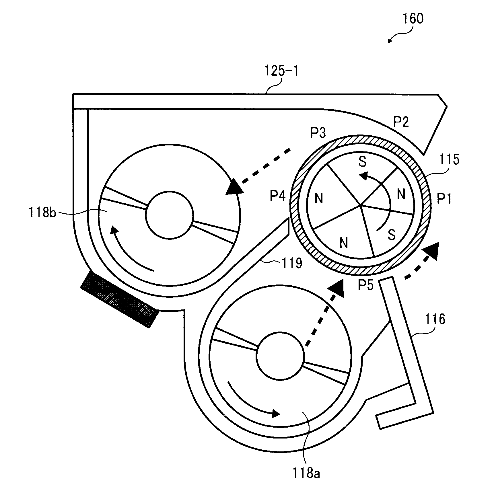
[0170]FIG. 20 illustrates action of the magnetic poles of the development roller 115 in the present embodiment. In FIG. 20, reference characters P1 through P5 represent the magnetic poles of the magnet roller 133. For example, the magnetic poles P1 through P5 are respectively S, N, S, N, and N poles. The magnetic poles P1 through P5 serve as a development pole, a developer conveyance pole, another developer conveyance pole, an upstream release pole, and an attraction pole (downstream release pole). The amount of the developer carried on the development sleeve 132 is adjusted by the doctor blade 116, after which the developer is further transported as the development sleeve 132 rotates.

[0171]After developing the lat...


PUM


Abstract

A development device including a developer container, a developer bearer, a magnetic field generator, a developer agitator to supply the developer to the developer bearer, and a developer regulator to adjust a layer thickness of the developer carried on the developer bearer. Multiple oval recesses oblique to the axial direction of the developer bearer are formed in the outer circumferential surface of the developer bearer and arranged in a circumferential direction and the axial direction thereof. An upstream inner wall of the recess in the rotational direction of the developer bearer applies a force to the developer as the developer bearer rotates, and an angle between a long axis of the recess and the axial direction is set so that the force applied by the upstream inner wall of the recess has a component in a direction substantially identical to the developer conveyance direction of the developer agitator.

Description

CROSS-REFERENCE TO RELATED APPLICATIONS[0001]This patent application is based on and claims priority pursuant to 35 U.S.C. §119 to Japanese Patent Application Nos. 2010-198341 filed on Sep. 3, 2010, 2010-198343 filed on Sep. 3, 2010, and 2010-198348 filed on Sep. 3, 2010 in the Japan Patent Office, the entire disclosure of which is hereby incorporated herein by reference.FIELD OF THE INVENTION[0002]The present invention generally relates to a development device to developer a latent image into a toner image, a process cartridge including the same, and an electrophotographic image forming apparatus, such as a copier, a printer, a facsimile machine, or a multifunction machine having at least two of these capabilities, that includes the same.BACKGROUND OF THE INVENTION[0003]Generally, electrophotographic image forming apparatuses such as copiers, printers, facsimile machines, or multifunction machines including those capabilities include a development device to develop latent images fo...

Claims


Application Information

Patent Timeline
Patent Type & Authority Applications(United States)
IPC IPC(8): G03G15/09
CPCG03G15/0928G03G15/0818
Inventor TAGUCHI, NOBUYUKIMASUDA, KATSUMIOZEKI, TAKAMASASATOH, YUUKIHAYASHI, TOSHIKIKOETSUKA, KYOHTAKOJIMA, TOSHIOOHSAWA, MASAYUKIKAMIYA, NORIYUKITERASAKA, TAKUMI
Owner RICOH KK
Why Eureka
Try Eureka