
Air battery

a battery and air technology, applied in the field of air batteries, can solve problems such as air battery deterioration, and achieve the effect of inhibiting water ingress and good battery performan

Active Publication Date: 2012-03-08
TOYOTA JIDOSHA KK
View PDF1 Cites 6 Cited by
  • Summary
  • Abstract
  • Description
  • Claims
  • Application Information

AI Technical Summary

Benefits of technology

The present invention relates to an air battery that uses oxygen as a cathode active material and has a hydrophobic nature to prevent water from entering the battery. The technical effect of the invention is to maintain the performance of the battery and keep water out from the housing. The air battery has a power section with an air electrode, an anode containing an alkali metal, and an electrolyte layer conducting ions between the air electrode and the anode. An oxygen-containing solvent showing both hydrophobic nature and oxygen solubility is used as the electrolyte layer. The oxygen supply portion is arranged away from the electrolyte layer to inhibit ingress of water. The air battery has both ion conductive property and hydrophobic nature, and the oxygen supply portion can supply oxygen rapidly into the oxygen-containing solvent. The housing has an inlet and an outlet port for the oxygen-containing solvent, and a cyclic path being disposed outside the housing to circulate the oxygen-containing solvent. The electrolyte layer is insoluble in the oxygen-containing solvent and has a smaller specific gravity than that of the oxygen-containing solvent, and the power section is arranged at the upper side in the vertical direction of the oxygen-containing solvent such that the anode is arranged at the upper side in the vertical direction. The air battery may have a mode where the electrolyte layer is insoluble in the oxygen-containing solvent and has a smaller specific gravity than that of the oxygen-containing solvent, and the power section is arranged at the upper side in the vertical direction of the oxygen-containing solvent. The invention provides an air battery with hydrophobic nature that prevents water from entering the battery.

Problems solved by technology

If the water and the anode react, it predicts that the air battery may be deteriorated.

Method used


Image

  • Air battery
  • Air battery
  • Air battery

Examples


first embodiment

1. First Embodiment of the Invention

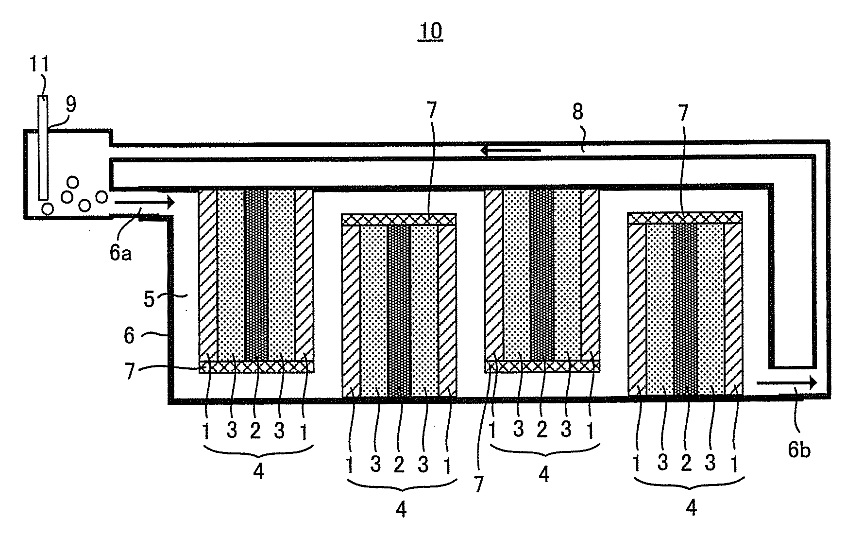
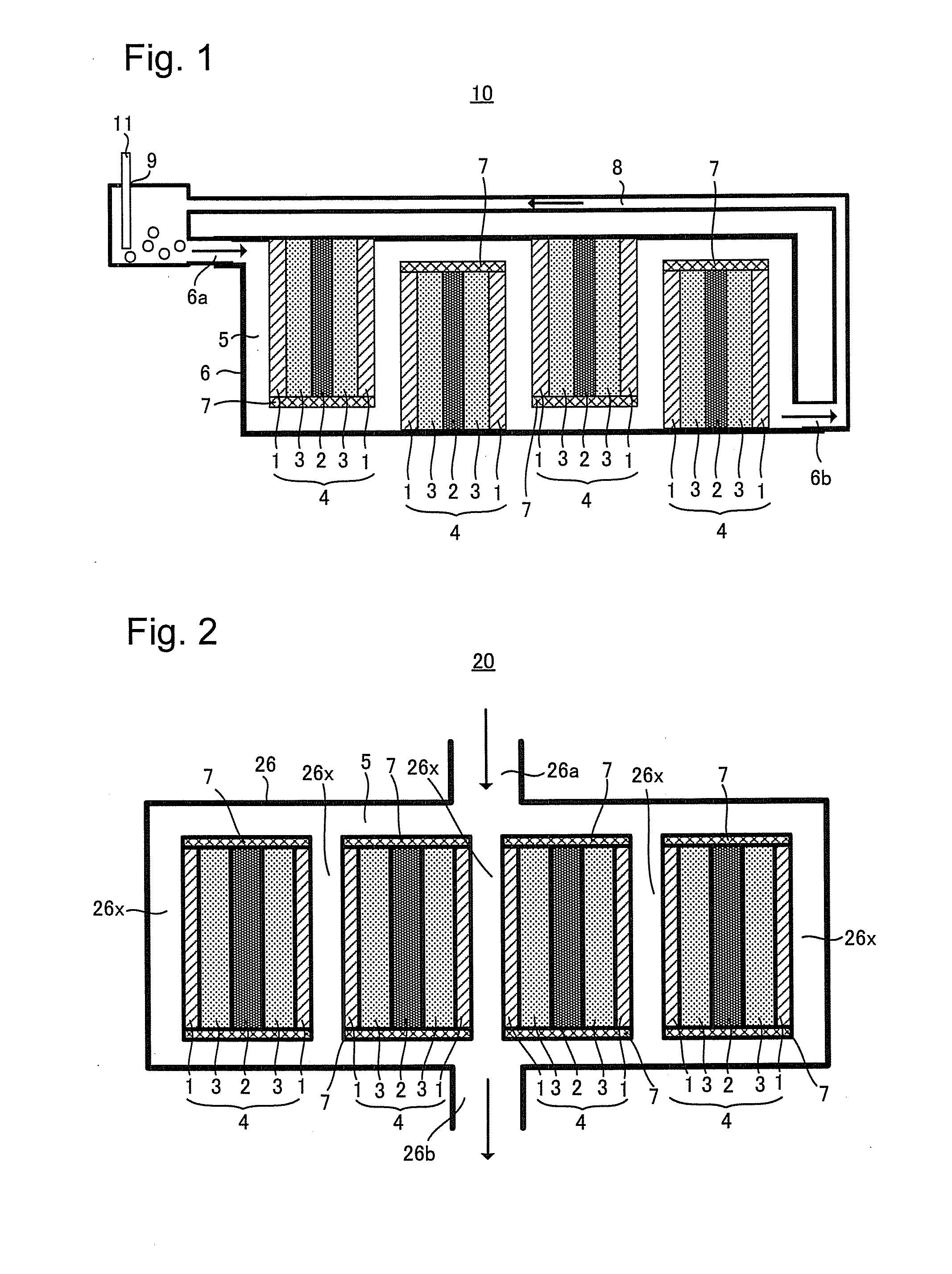
[0051]FIG. 1 is a cross-sectional view schematically showing an embodiment of the air battery 10 of the present invention. As shown in FIG. 1, the air battery 10 comprises: power sections 4 each comprising: air electrodes (namely, cathode layers) 1, an anode 2, and electrolyte layers 3 sandwiched between the air electrode 1 and the anode 2; an oxygen-containing solvent 5; and a housing 6 being configured to incorporate a plurality of the power sections 4, 4, . . . and the oxygen-containing solvent 5. In the air battery 10, since the hydrophobic oxygen-containing solvent 5 is filled in the housing 6, it is possible to inhibit ingress of water into the housing 6. Moreover, the oxygen-containing solvent 5 is arranged between an oxygen supply portion 9 and the electrolyte layer 3 and exhibits not only hydrophobic nature but also oxygen solubility so that the oxygen-containing solvent 5 can supply oxygen dissolved therein to the air electrode 1 and inh...

second embodiment

2. Second Embodiment of the Invention

[0081]FIG. 2 is a cross-sectional view schematically showing an embodiment of the air battery 20 of the invention. In FIG. 2, to the elements having the same structure as those in the air battery 10, the same reference numerals as used in FIG. 1 are given, and the explanation thereof is omitted.

[0082]As shown in FIG. 2, the air battery 20 comprises: a plurality of power sections 4, 4, . . . comprising air electrode(s) 1, an anode 2, and electrolyte layer(s) 3 sandwiched between the air electrode 1 and the anode 2; an oxygen-containing solvent 5; and a housing 26 being configured to incorporate the plurality of power sections 4 and an oxygen-containing solvent 5. In the air battery 20, since the housing 26 is filled with an hydrophobic oxygen-containing solvent 5, ingress of water into the housing 26 can be inhibited. In addition, since the power section 4 is incorporated in the housing 26 such that the air electrode 1 is in contact with the oxyge...

third embodiment

3. Third Embodiment of the Invention

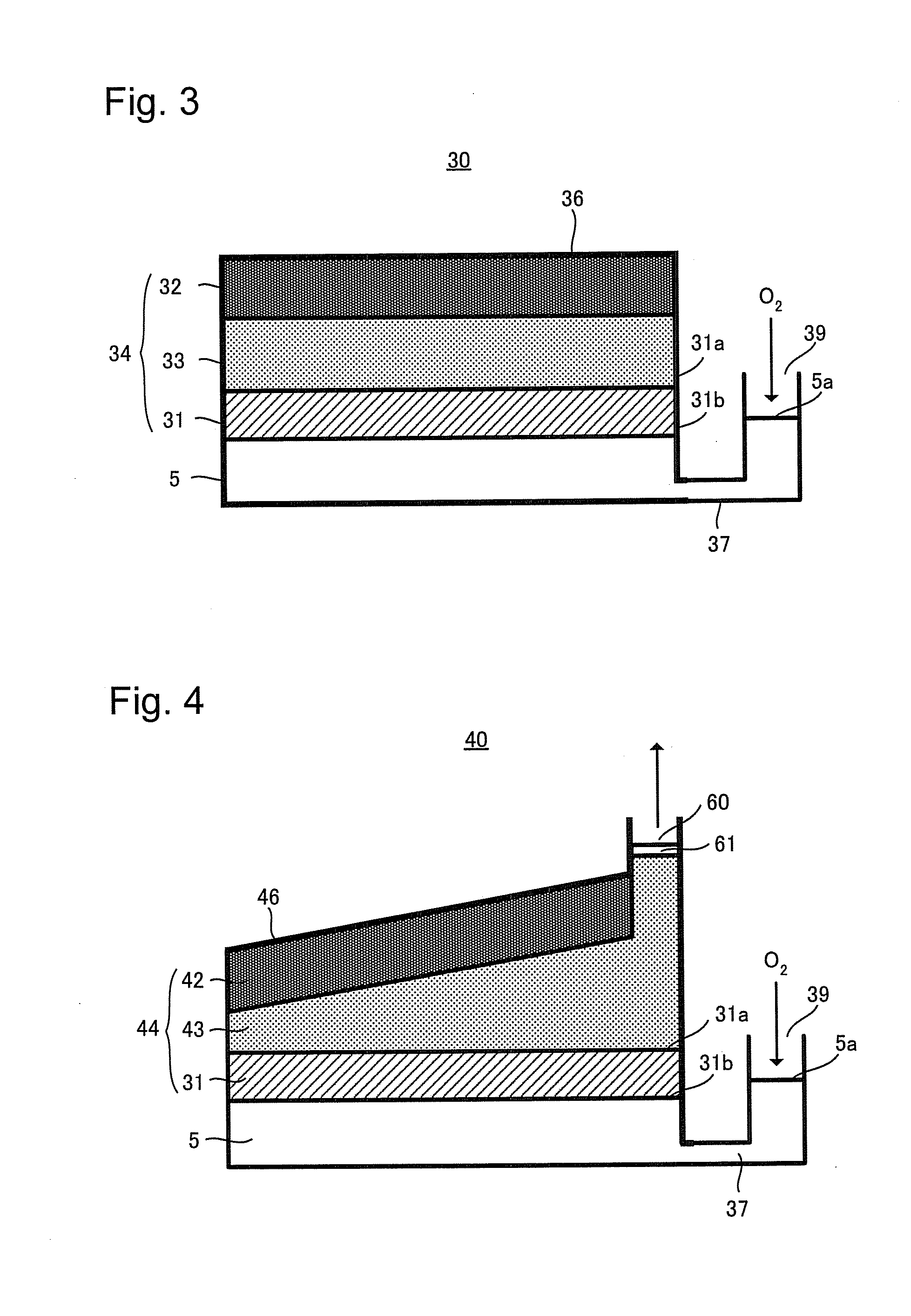
[0089]FIG. 3 is a cross-sectional view schematically showing an embodiment of the air battery 30 of the present invention. In FIG. 3, to the elements having the same structure as those in the air battery 10, the same reference numerals as those used in FIG. 1 are given and the explanation thereof is omitted.

[0090]As shown in FIG. 3, the air battery 30 comprises: a power section 34 comprising an air electrode 31, an anode 32, and an electrolyte layer 33 sandwiched between the air electrode 31 and the anode 32; an oxygen-containing solvent 5; and a housing 36 being configured to incorporate the power section 34 and the oxygen-containing solvent 5. The specific gravity of the electrolytic solution provided in the electrolyte layer 33 is smaller than that of the oxygen-containing solvent 5. The power section 34 is arranged at the upper side in the vertical direction of the oxygen-containing solvent such that the anode 32 is arranged at the upper side ...


PUM

PropertyMeasurementUnit
pressureaaaaaaaaaa
hydrophobicaaaaaaaaaa
solubilityaaaaaaaaaa

Abstract

The present invention provides an air battery which can maintain a good performance and inhibit ingress of water into the housing. An air battery comprising: a power section which comprises: an air electrode, an anode containing an alkali metal, and an electrolyte layer conducting ions between the air electrode and the anode; an oxygen-containing solvent showing both hydrophobic nature and oxygen solubility; a housing being configured to incorporate the power section and the oxygen-containing solvent; and an oxygen supply portion being configured to supply oxygen gas to the oxygen-containing solvent, the oxygen-containing solvent being arranged between the oxygen supply portion and the electrolyte layer.

Description

TECHNICAL FIELD[0001]The present invention relates to an air battery.BACKGROUND ART[0002]An air battery is a battery employing oxygen as a cathode active material; at the time of discharge, air is introduced from outside the battery. So, compared with other type of batteries which incorporate active materials for both cathode and anode, it is possible to enlarge the occupancy rate of the anode active material in the battery case. Hence, in principle, such an air battery has features that dischargeable electric power is large, besides, as downsizing and weight saving can be easily realized. In addition, oxidation power of oxygen to be employed as the cathode active material is strong so that the electromotive force is relatively high. Moreover, since oxygen is a clean resource the amount of which is not limited, the air battery is environmentally-friendly. As above, air battery has many advantages; therefore it is expected to be used for batteries for mobile devices, electric vehicle...

Claims


Application Information

Patent Timeline
Patent Type & Authority Applications(United States)
IPC IPC(8): H01M12/06
CPCH01M12/065H01M12/06
Inventor NAKANISHI, SHINJIIMAI, HIROTOSHI
Owner TOYOTA JIDOSHA KK
Learn More