Clavicle Bone Plate

a clavicle bone plate and clavicle bone technology, applied in the field of bone plate, can solve the problems of clavicle fractures, clavicle bone plate damage, and unaesthetically pleasing results, and achieve the effect of reducing the overall thickness, weight and cost of the material, and enhancing durability and strength

Inactive Publication Date: 2012-03-08
ADVANCED ORTHOPAEDIC SOLUTIONS
View PDF10 Cites 72 Cited by
  • Summary
  • Abstract
  • Description
  • Claims
  • Application Information

AI Technical Summary

Benefits of technology

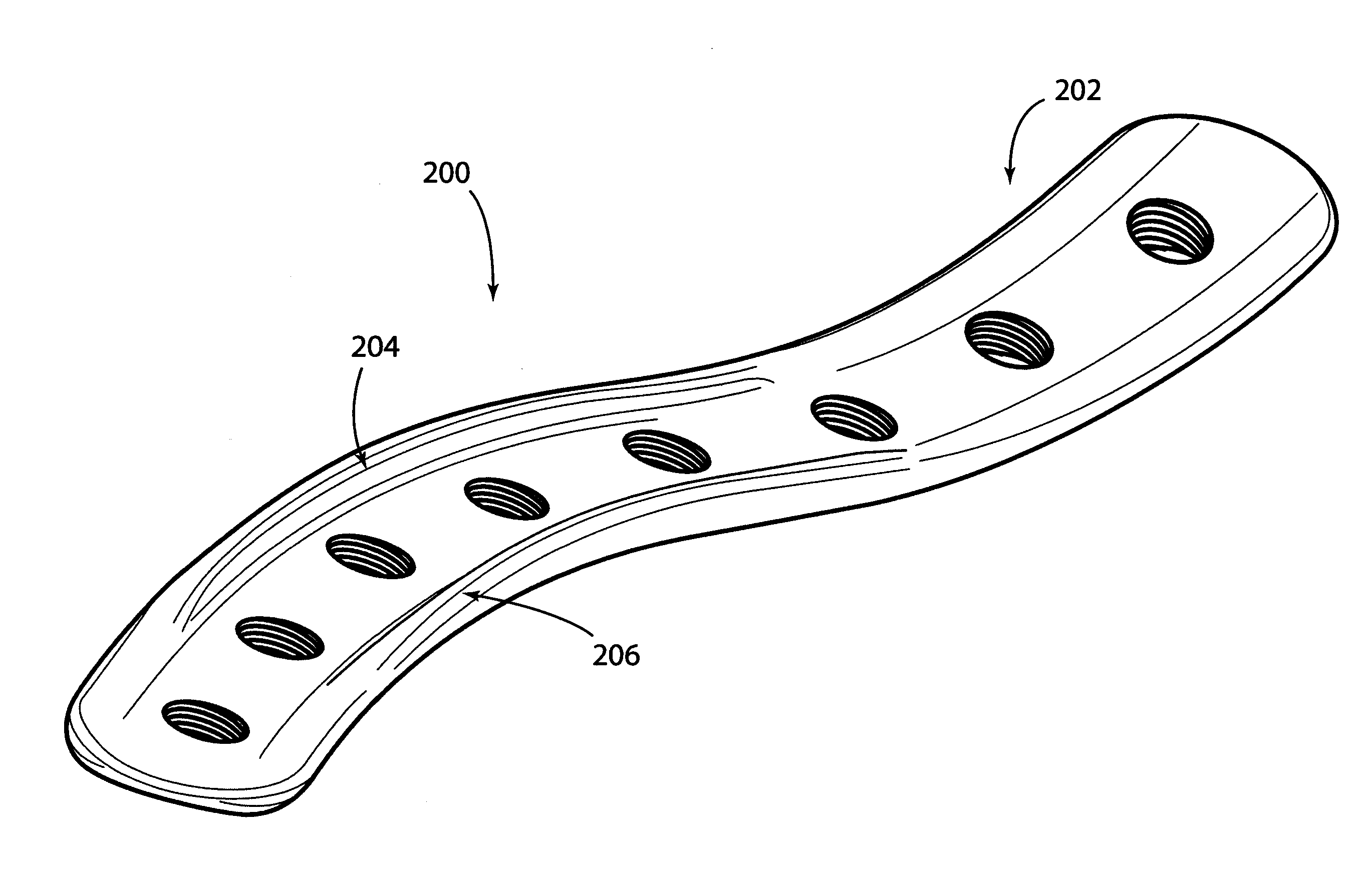
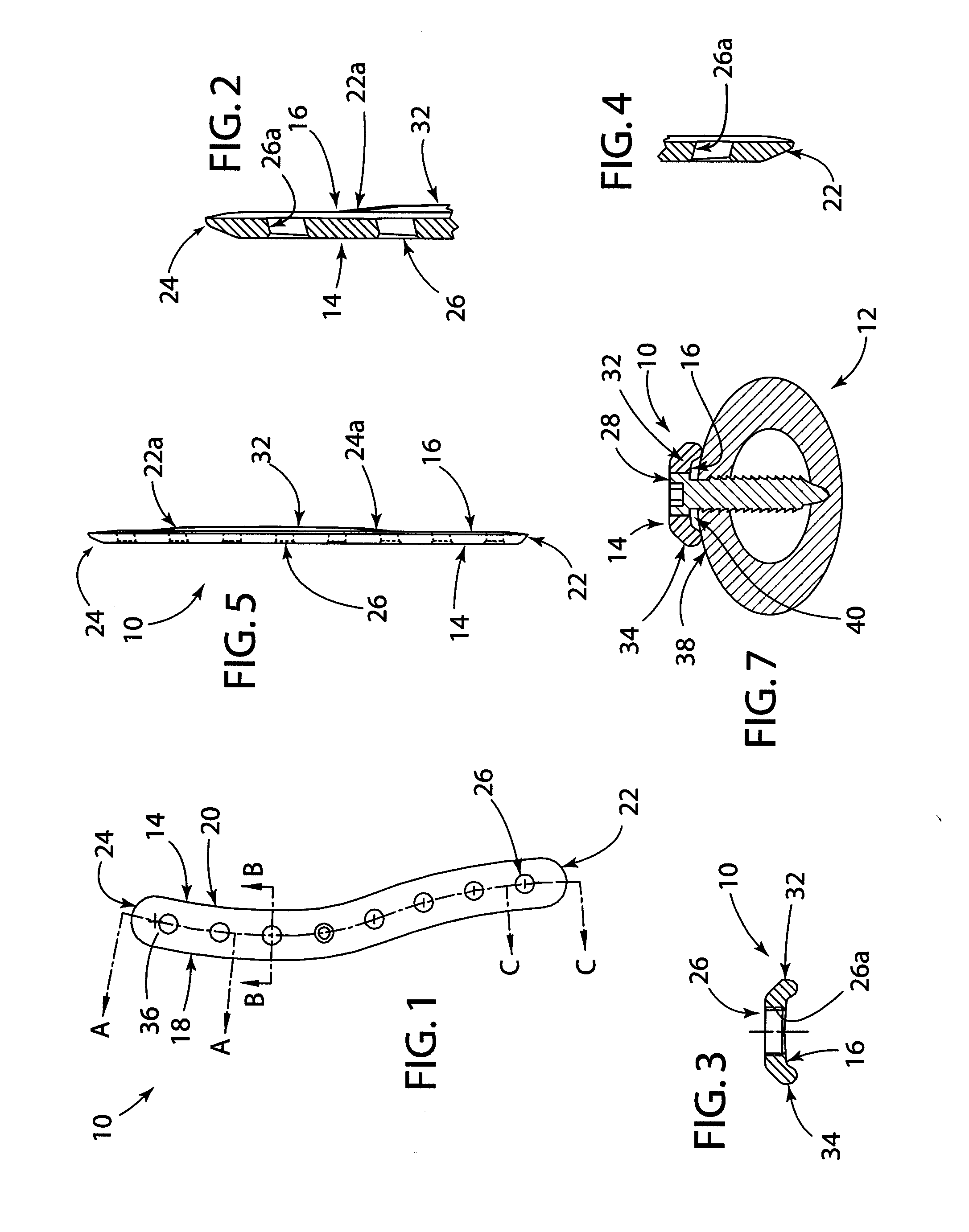
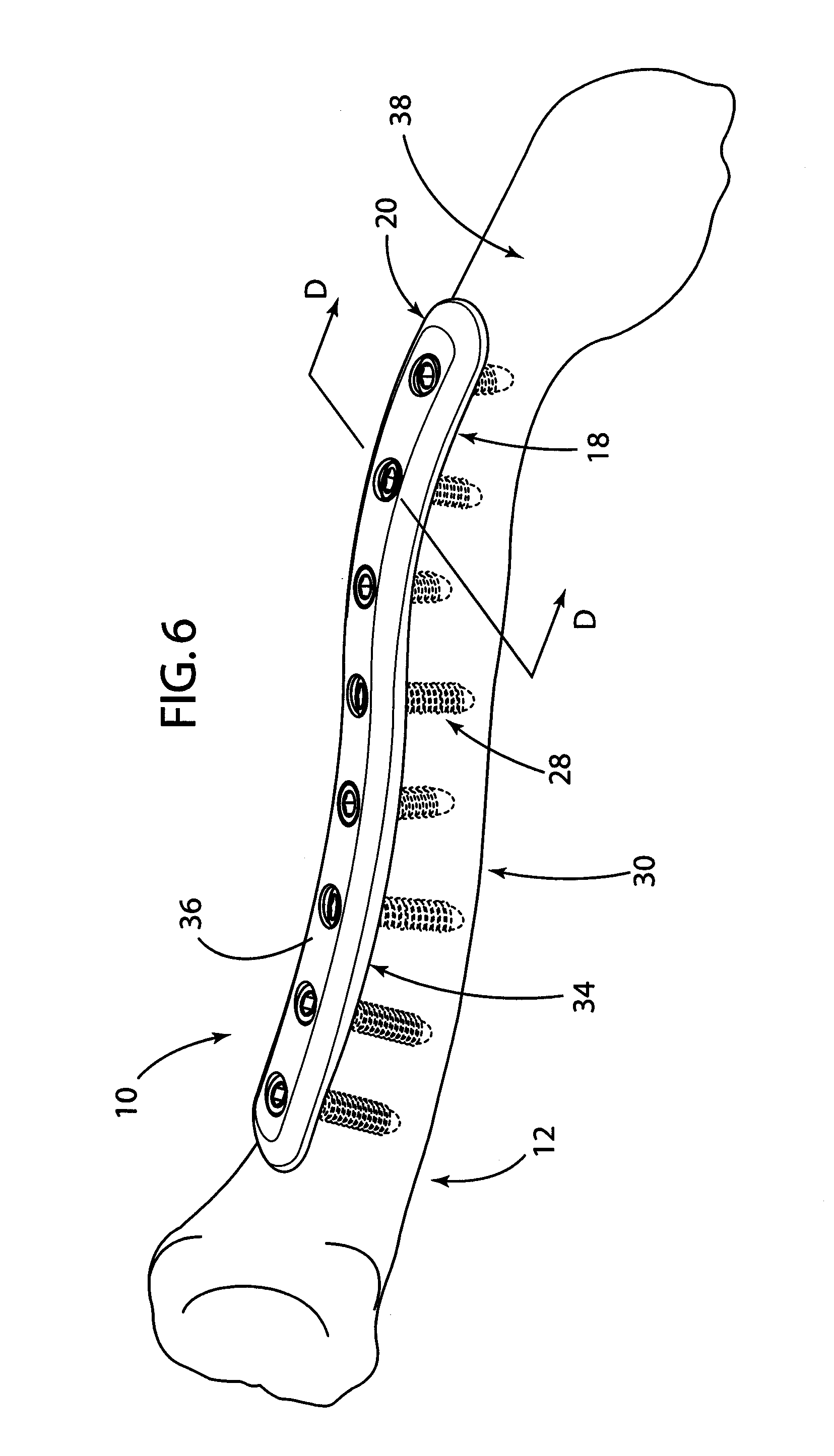
[0008]A bone plate for affixation to a bone for treating bone fractures, especially clavicle fractures. The clavicle bone plate may include an elongate body having a first end portion at a proximal end and a second end portion toward a distal end. The clavicle bone plate may include one or more curved portions that roughly conform to the surface and/or anatomical curvature of the clavicle, especially the surface and/or anatomical curvature of the shaft of the clavicle. One or more openings may be provided in the body, the first end portion, and/or the second end portion for receiving an anchoring member, such as a bone screw, for fastening at least a portion of the clavicle bone plate onto the clavicle, especially in proximity to the fracture site. The clavicle bone plate may also provide at least one, and more preferably at least two sp

Problems solved by technology

Unfortunately, clavicle fractures are common occurrences.
A drawback of some of the known clavicle bone plates is that they are typically composed of relatively thick metallic plates that, after being attached to the fractured clavicle, may be clearly visible against the underside of the skin of the patient.
This outcome is

Method used


Image

  • Clavicle Bone Plate
  • Clavicle Bone Plate
  • Clavicle Bone Plate

Examples


Embodiment Construction

[0040]The following detailed description of the invention is merely exemplary in nature and is in no way intended to limit the invention, its application, or uses.

[0041]For the purposes of promoting an understanding of these principles in accordance with the disclosure, reference will now be made to the embodiments illustrated in the drawings and specific language will be used to describe the same. It will nevertheless be understood that no limitation of the scope of the disclosure is thereby intended. Any alterations and further modifications of the inventive features illustrated herein, and any additional applications of the principles of the disclosure as illustrated herein, which would normally occur to one skilled in the relevant art having possession of this disclosure, are to be considered within the scope of the disclosure claimed.

[0042]Before the present apparatus and methods for treating a bone fracture are disclosed and described, it is to be understood that this disclosu...


PUM


Abstract

A bone plate for treating clavicle fractures. The bone plate may include an elongated body having one or more curved portions that roughly conform to the surface and/or anatomical curvature of the clavicle. One or more openings may be provided for receiving an anchoring member, such as a bone screw, for fastening at least a portion of the bone plate onto the clavicle. The bone plate may provide at least one rail member extending along a portion of the body of the bone plate. The bone plate, when affixed to the clavicle, permits the rail member to rest upon the outer surface of the clavicle, thus providing an area defining a cavity formed between an outer surface of the clavicle and a bottom surface of the body of the bone plate, and thus allowing blood to circulate against and around the clavicle.

Description

CROSS-REFERENCE TO RELATED APPLICATIONS[0001]This application claims the benefit of U.S. Provisional Application Ser. No. 61 / 312,245 filed Mar. 10, 2010 which is now expired.BACKGROUND OF THE INVENTION[0002]1. Field of the Invention[0003]The present disclosure relates generally to bone treatment devices, and more particularly to bone plates for stabilizing clavicle fractures.[0004]2. Description of Related Art[0005]The clavicle is a doubly curved short bone that connects the arm (i.e., the upper limb) to the body (i.e., the trunk), located directly above the first rib and is often referred to as a collarbone. Unfortunately, clavicle fractures are common occurrences. Clavicle fractures, that is a broken collarbone, can occur in children and adolescents, athletes, or during many types of accidents and falls. Often clavicle fractures are treated using a plate-and-screw fixation or intramedullary devices. The plate-and-screw devices typically include a flat steel bone plate that is affi...

Claims


Application Information

Patent Timeline
IPC IPC(8): A61B17/80A61B17/88
CPCA61B17/8085A61B17/8061
Inventor EPPERLY, SCOTTRAVEN, RAYMOND B.
Owner ADVANCED ORTHOPAEDIC SOLUTIONS
Why Eureka
Try Eureka