Method and apparatus for assisting pivot motion of a handle in a floor treatment device

a technology of floor treatment device and handle, which is applied in the direction of suction cleaners, brushes, metal-working hand tools, etc., can solve the problems and affecting the use of the floor treatment device. , to achieve the effect of reducing the effective weight of the handle to the user and facilitating the use of the floor treatment devi

Active Publication Date: 2012-03-15
SHARKNINJA OPERATING LLC
View PDF5 Cites 117 Cited by
  • Summary
  • Abstract
  • Description
  • Claims
  • Application Information

AI Technical Summary

Benefits of technology

[0002]Aspects of the invention provide for a floor treatment device having a handle attached to a floor treatment portion such that the handle is pivotable relative to the floor treatment portion, e.g., in side-to-side directions. Also included is a pivot assist device that urges the handle to move from one pivot position to another pivot position. For example, in one embodiment, if the handle is pivoted from a center position to a side position, e.g., to steer the floor treatment portion left or right, the pivot assist device may exert a force on the handle that tends to return the handle from the side position back to the center position. This feature may make handling of the floor treatment device easier for the user, e.g., if the handle includes a relatively heavy dirt container and fan unit on the handle, the pivot assist device may help support the weight of the handle when pivoting the handle to the side. That is, in some cases, when a user pivots a handle and attached dirt container and fan to the side, the weight of the handle and attached components may make returning the handle to its center, upright position difficult. The repeated lifting of the weight of the handle, dirt container, fan, etc., from side pivoted positions back to the center, upright position can be tiresome to a user. However, the pivot assist device in some embodiments can reduce the effective weight of the handle to the user because of the force the pivot assist device exerts on the handle to help the user lift the handle from a side pivoted position to a center position.

Problems solved by technology

That is, in some cases, when a user pivots a handle and attached dirt container and fan to the side, the weight of the handle and attached components may make returning the handle to its center, upright position difficult.
The repeated lifting of the weight of the handle, dirt container, fan, etc., from side pivoted positions back to the center, upright position can be tiresome to a user.
However, the pivot assist device in some embodiments can reduce the effective weight of the handle to the user because of the force the pivot assist device exerts on the handle to help the user lift the handle from a side pivoted position to a center position.

Method used


Image

  • Method and apparatus for assisting pivot motion of a handle in a floor treatment device
  • Method and apparatus for assisting pivot motion of a handle in a floor treatment device
  • Method and apparatus for assisting pivot motion of a handle in a floor treatment device

Examples


Embodiment Construction

[0022]It should be understood that aspects of the invention are described herein with reference to the figures, which show illustrative embodiments in accordance with aspects of the invention. The illustrative embodiments described herein are not necessarily intended to show all aspects of the invention, but rather are used to describe a few illustrative embodiments. Thus, aspects of the invention are not intended to be construed narrowly in view of the illustrative embodiments. In addition, it should be understood that aspects of the invention may be used alone or in any suitable combination with other aspects of the invention.

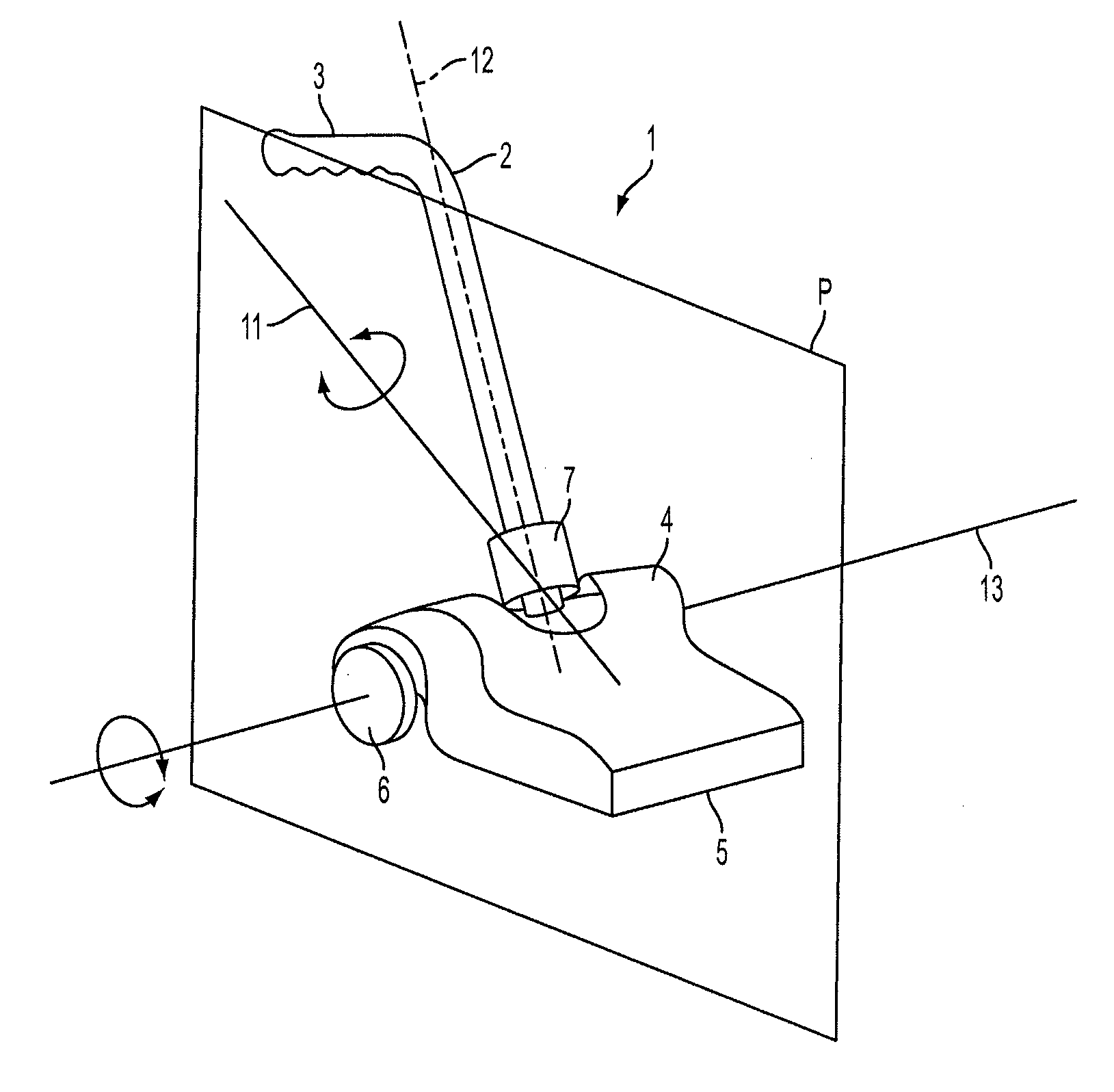
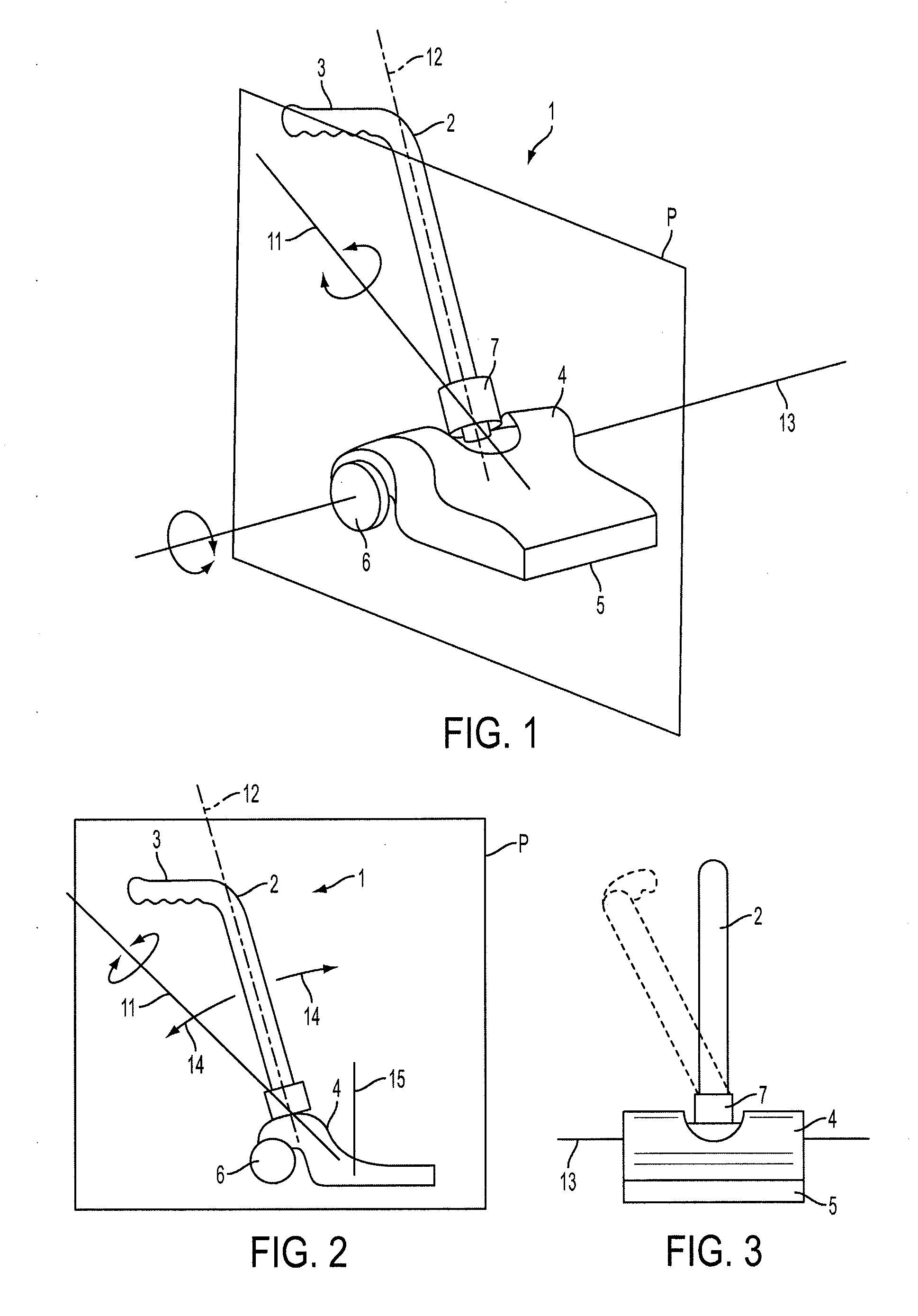
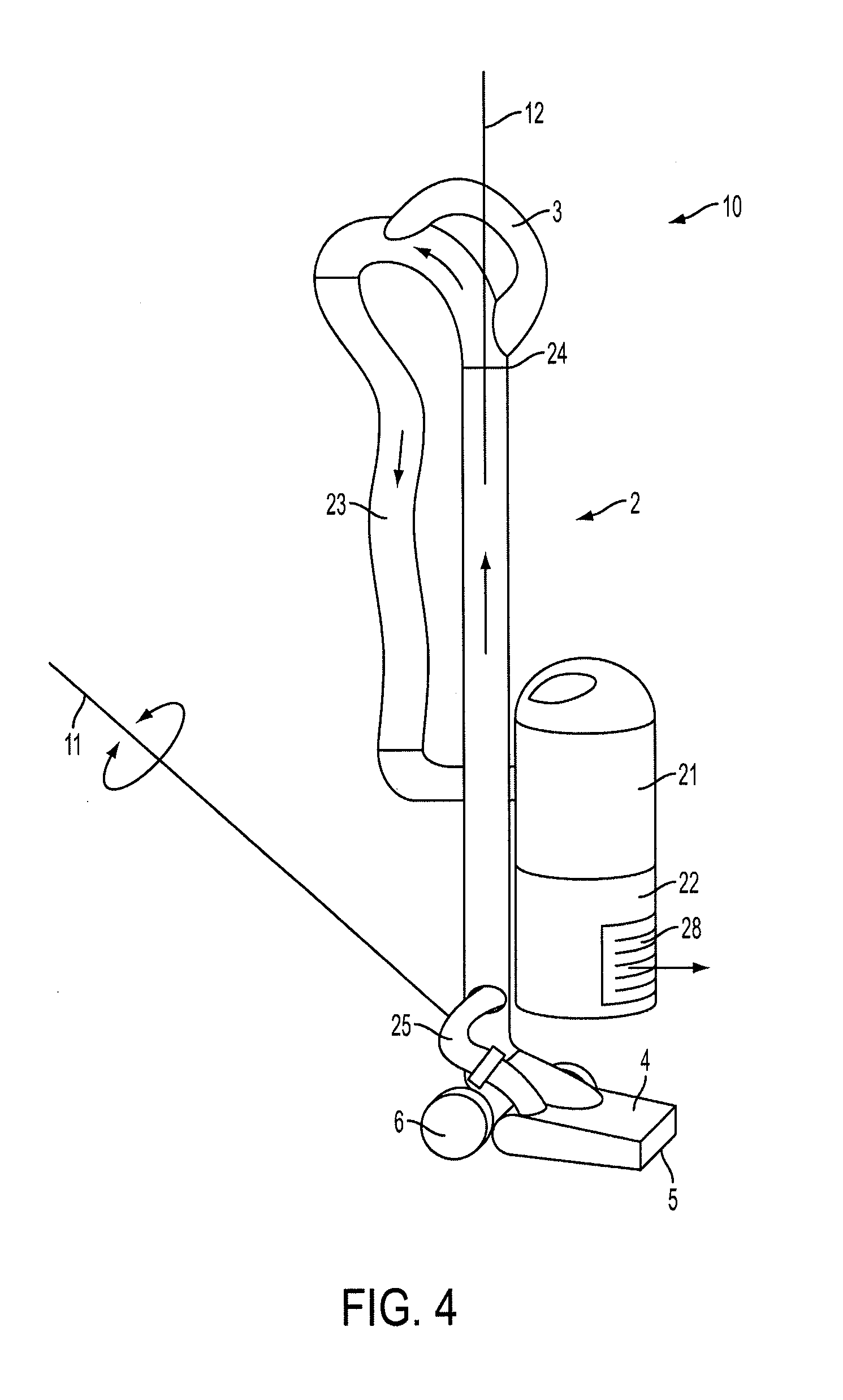
[0023]Embodiments of the invention provided herein are directed to cleaning appliance systems which are capable of cleaning floors and / or other surfaces. Examples of surface cleaners include steam mops, portable steam cleaners, vacuum cleaners, floor sweepers, mops or other floor wiping devices, among others. In one aspect of the invention, a floor treatment ...


PUM


Abstract

A method and apparatus for influencing movement of a handle of a floor treatment device, such as a vacuum. The floor treatment device may include a handle portion that is attached to a base, which includes a floor treatment portion. The handle portion may be pivotally movable about a rotation axis relative to the base between at least first and second positions, where the rotation axis lies in a vertical plane that includes a longitudinal axis of the handle when the handle portion is in the first position and the longitudinal axis is a non-vertical position. A pivot assist device may apply a bias to the handle portion that urges the handle portion to move from the second position to the first position, e.g., to help support the weight of the handle when a user steers the floor treatment device across a floor.

Description

BACKGROUND[0001]Floor treatment devices, such as floor sweepers, vacuums, steam cleaners, mops, tools for applying floor wax or other materials, etc., commonly have a handle attached to a floor treatment portion, such as a cleaning head. The handle and cleaning head of such devices are commonly arranged so that the user can manipulate the cleaning head on the floor without requiring the user to stoop or bend at the waist. It is also common for the handle of such devices to be capable of pivoting, e.g., so that a floor contacting surface of the cleaning head can remain in contact with the floor as the user pushes and pulls on the handle to move the cleaning head across the floor. For example, U.S. Patent Publication 2009 / 0089969 shows an upright vacuum cleaner that has a cleaner body 10 with a handle 11 that is pivotable relative to a suction port assembly 40. As shown in FIG. 4 of U.S. Patent Publication 2009 / 0089969, the cleaner body 10 and handle 11 appear to be pivotable in forwa...

Claims


Application Information

Patent Timeline
Patent Type & Authority Applications(United States)
IPC IPC(8): A47L9/00B25G1/00B08B1/00
CPCA47L9/009A47L9/325A47L9/242
Inventor SIMONELLI, DAVID J.THORNE, JASON
Owner SHARKNINJA OPERATING LLC
Why Eureka
Try Eureka