Rechargeable electric tool

a rechargeable electric tool and handle technology, applied in the field of rechargeable electric tools, can solve the problems of low sealing performance between the handle housing and the battery cover, the size of the rechargeable electric tool becomes also larger, and the battery cover becomes larger, so as to improve the water-proof performance of the battery pack

Active Publication Date: 2012-03-15
MAKITA CORP
View PDF2 Cites 53 Cited by
  • Summary
  • Abstract
  • Description
  • Claims
  • Application Information

AI Technical Summary

Benefits of technology

[0016]According to the first aspect of the present invention, the rechargeable electric tool as an embodiment of the invention can prevent rainwater and the like from entering the battery through the coupling part between the battery holder and the battery pack toward the battery. Further, rainwater entering the battery from the outer face of the battery pack can be prevented. Consequently, waterproof performance to the battery pack is improved.
[0017]Further, since the two divided covers coupled each other are slidable in different direction, it is unnecessary to provide a space for a turning operation of the waterproof cover. Therefore, even when the waterproof cover of the two divided covers is provided, the rechargeable electric tool can be made compact.
[0018]According to the second aspect of the present invention, in the rechargeable electric tool as an embodiment of the invention, the two divided covers are sealed by the coupling faces thereof in the attached state where the coupling part and the battery pack are covered with the waterproof cover. Therefore, rainwater and the like is prevented from entering the inside of the waterproof cover through the gap between the coupling faces.
[0019]According to the third aspect of the present invention, in the rechargeable electric tool as an embodiment of the invention, in the attached state, the first seal member provided integrally with at least one of the divided covers seals the gap between the coupling faces. Therefore, rainwater and the like is prevented from entering the inside of the waterproof cover through the gap between the coupling faces.
[0020]According to the forth aspect of the present invention, the rechargeable electric tool as an embodiment of the invention, in the attached state of the two divided covers, the gap between the opening of the waterproof cover and the battery holder can be closely sealed by the seal face of the battery holder. Therefore, rainwater and the like can be prevented from entering the inside of the waterproof cover through the gap between the coupling faces.
[0021]According to the fifth aspect of the present invention, in the rechargeable electric tool as an embodiment of the invention, in the attached state, the second seal member seals the gap between the waterproof cover and the seal face. Therefore, rainwater and the like is prevented from entering the inside of the waterproof cover through the gap between the coupling faces.

Problems solved by technology

Consequently, the battery cover is not tightly attached to the handle housing, which leads low performance of the sealing between the handle housing and the battery cover.
It is therefore concerned that the battery cover becomes larger, and the size of the rechargeable electric tool becomes also larger.

Method used


Image

  • Rechargeable electric tool
  • Rechargeable electric tool
  • Rechargeable electric tool

Examples


first embodiment

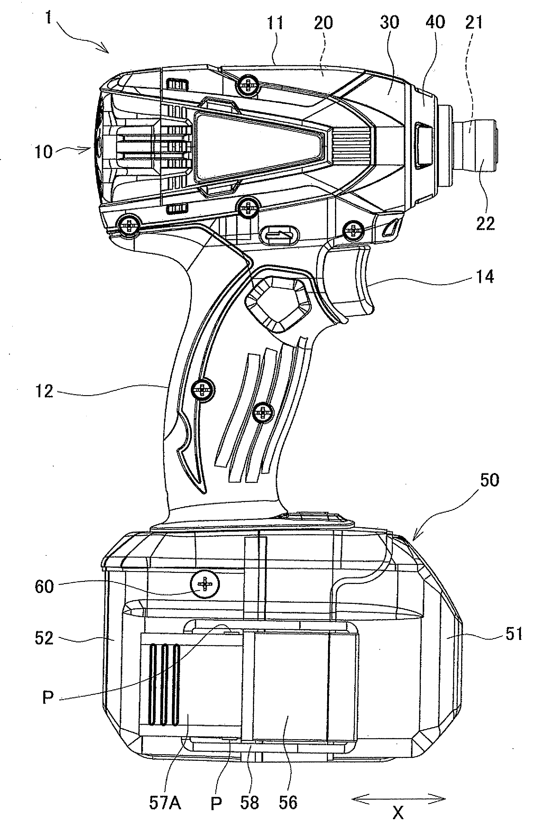
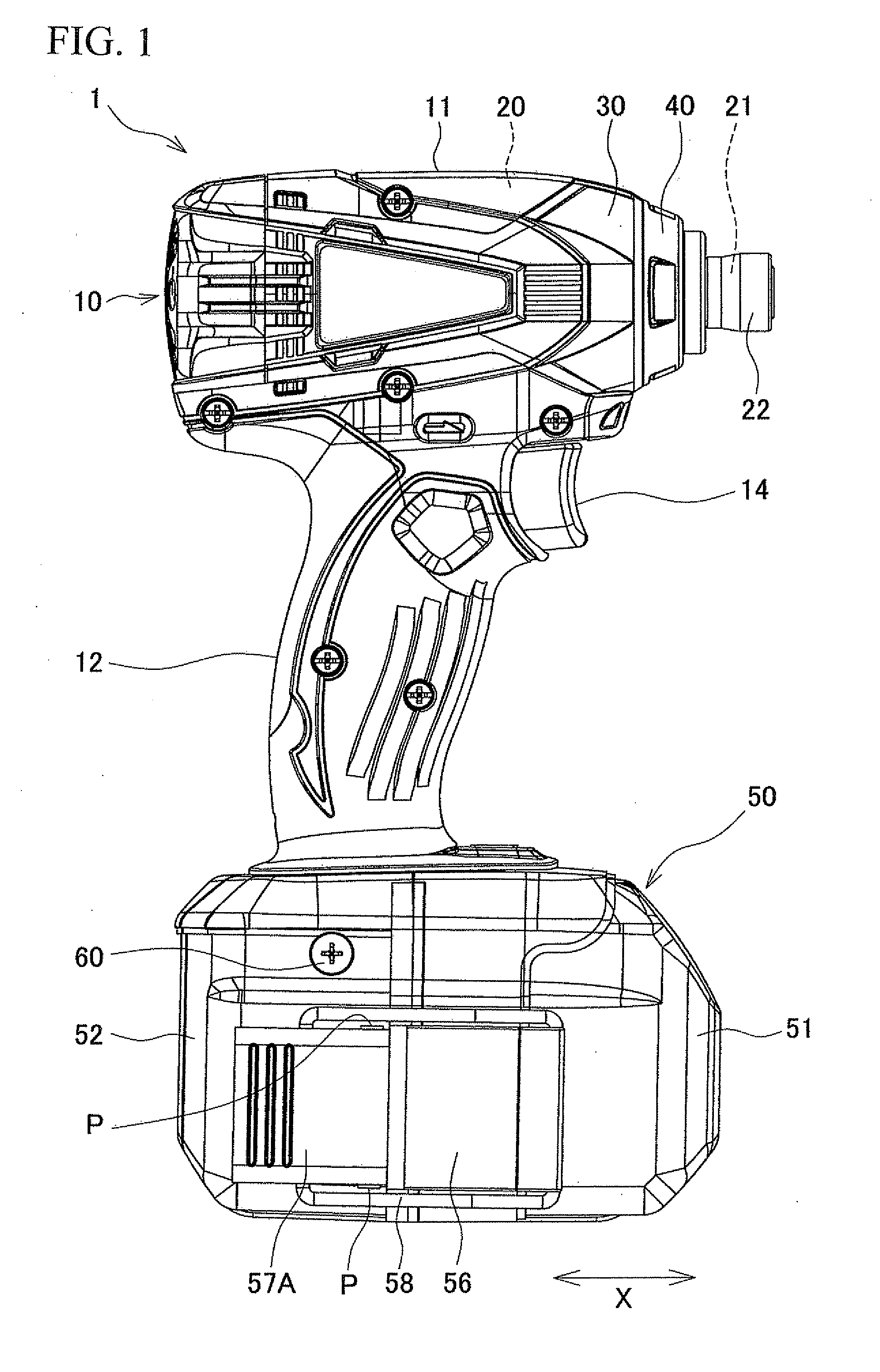
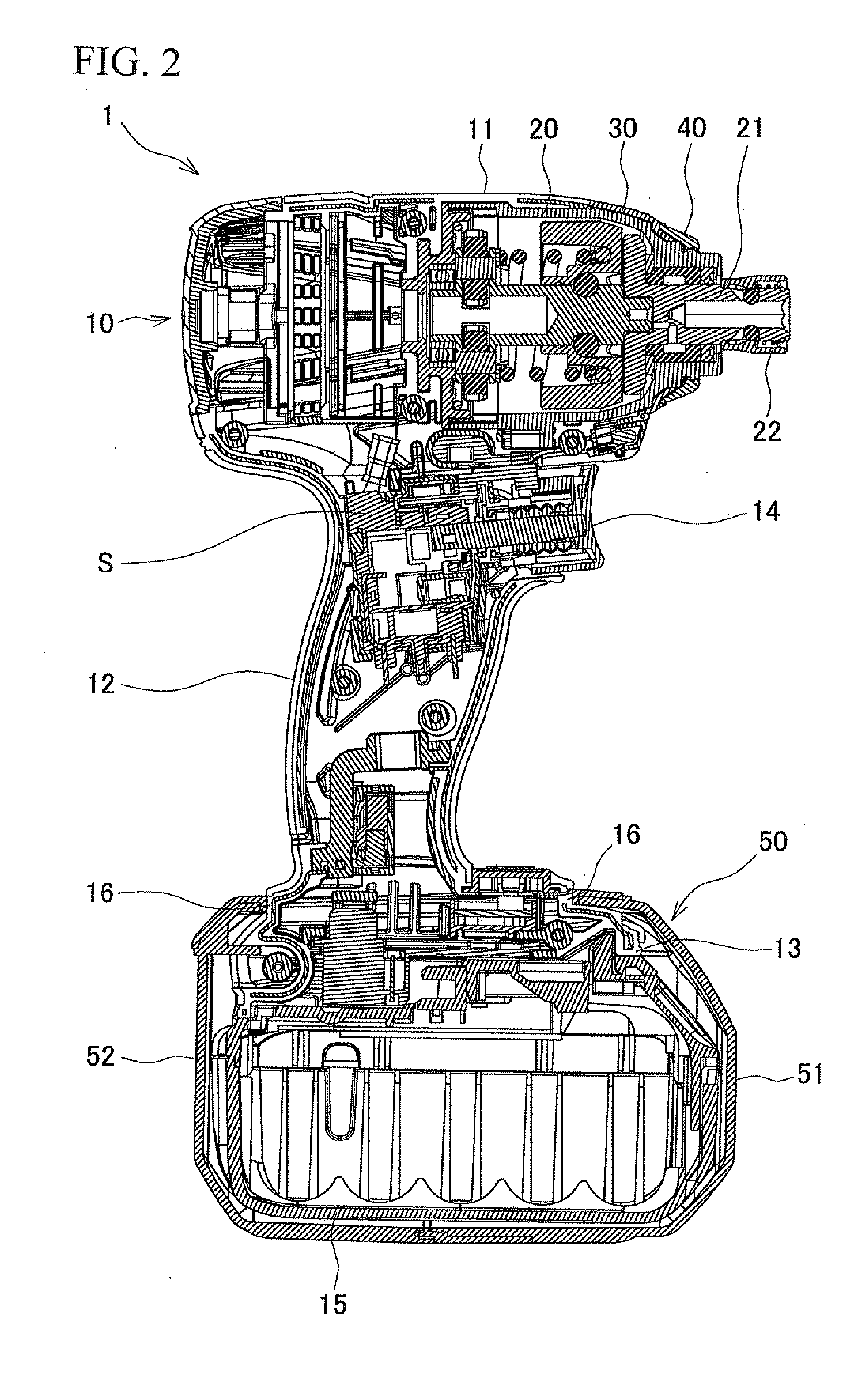
[0034]A first embodiment of the present invention will be described with reference to FIGS. 1 to 5. As illustrated in FIG. 1, an impact driver 1 has a body housing 10, a hammer case 20, a cover 30, a bumper 40, and a waterproof cover 50.

[0035]The body housing 10 is formed by assembling right and left halved housings made of resin and has a body 11, a handle 12, and a battery holder 13. The body 11 has a tubular shape and extends in the longitudinal direction (the right side in FIGS. 1 and 2 is the front side, and the left side in FIGS. 1 and 2 is the rear side). In the body 11, a motor is housed.

[0036]As illustrated in FIGS. 1 and 2, the handle 12 extends from the body 11 in an almost T shape in side view of the impact driver 1, and a switch S having a trigger 14 which is provided on the handle 12. As illustrated in FIGS. 2 to 4, the battery holder 13 is provided below the handle 12, and a battery pack 15 is detachably inserted in the battery holder 13. The battery pack 15 is insert...

second embodiment

[0056]A second embodiment of the present invention will be described with reference to FIGS. 6 to 8. The same reference numeral is designated to the same configuration as that of the first embodiment and its description will not be repeated, and the same effect as that of the first embodiment will not be described. An impact driver 1A of the second embodiment has a waterproof cover 50A. The waterproof cover 50A has a front-side cover 51A and a rear-side cover 52A, and is formed so that it can be halved like the waterproof cover 50 of the first embodiment.

[0057]As shown in FIG. 7, in the rear-side cover 52A, a seal member supporting groove 61 is formed in a face S5 coupled to the front-side cover 51A. Both ends in the longitudinal direction of the seal member supporting groove 61 are open toward the seal face 16. A seal member 65 is fitted in the seal member supporting groove 61, projects from the seal member supporting groove 61, and is integrated with the coupling face S5. In addit...

third embodiment

[0063]A third embodiment of the present invention will be described with reference to FIGS. 9 to 11. The same reference numeral is designated to the same configuration as that of the first embodiment and its description will not be repeated, and the same effect as that of the first embodiment will not be described. An impact driver 1B of the third embodiment has a waterproof cover 50B. The waterproof cover 50B is also formed by a front-side cover 51B and a rear-side cover 52B so that it can be halved.

[0064]As shown in FIG. 10, in the rear-side cover 52B, three seal member supporting grooves 71 to 73 are formed in a face S7 to be coupled to the front-side cover 51B. The seal member supporting groove 71 is formed in the upper half on the left side of the coupling face S7 in front view of the rear-side cover 52B. The upper end of the seal member supporting groove 71 is open toward the seal face 16, and the lower end of the seal member supporting groove 71 has a bottom and is closed. On...


PUM


Abstract

The present invention provides a rechargeable electric tool in which a battery pack as a power supply slides in a battery holder formed in an end part of a housing. A bag-shaped waterproof cover covering the battery pack including a coupling part between the battery holder and the battery pack is formed by two divided covers which are separated to the front and rear sides in a slide attachment direction of the battery pack. Between the two divided covers, a coupling mechanism can be arbitrary operated in a coupling position or a coupling cancelling position. The coupling position is a position in which the divided covers are coupled to each other in an attached state where the coupling part and the battery pack are covered. The coupling cancelling position is a position in which coupling of the divided covers is cancelled.

Description

[0001]This application claims the entire benefit of Japanese Patent Application Number 2010-204677 filed on Sep. 13, 2010 and Japanese Patent Application Number 2011-005215 filed on Jan. 13, 2011, the entirety of which is incorporated by reference.BACKGROUND OF THE INVENTION[0002]1. Technical Field[0003]The present invention relates to a rechargeable electric tool having a battery pack as a power supply slides in a battery holder formed in an end part of a housing.[0004]2. Background Art[0005]Japanese Patent Application Laid-Open Publication No. H09-158483 discloses an invention of a battery cover which prevents infiltration of rainwater from a gap between a battery pack and a housing so that an adverse influence of rainwater is not exerted on an electric product housed in a rechargeable electric tool.[0006]The battery cover of Japanese Patent Application Laid-Open Publication No. H09-158483 is attached to the outside of a battery inserted in a lower part of a handle housing and is ...

Claims


Application Information

Patent Timeline
Patent Type & Authority Applications(United States)
IPC IPC(8): B25F5/02
CPCB25F5/02H01M2/1022Y02E60/12H01M2220/30H01M2/1094Y02E60/10H01M50/24
Inventor NAGASAKA, HIDENORIKUMAGAI, RYUNOSUKE
Owner MAKITA CORP
Why Eureka
Try Eureka