High-Efficiency Water Boiling Device

Inactive Publication Date: 2012-03-15
YANG SHUN CHI +4
View PDF2 Cites 20 Cited by
  • Summary
  • Abstract
  • Description
  • Claims
  • Application Information

AI Technical Summary

Benefits of technology

[0006]Therefore, it is an objective of the present invention to overcome the aforementioned shortcoming and deficiency of the prior art by providing a water boiling device that utilizes high frequency induction heating to heat cold water and has the advantages such as high heating efficiency, power saving, and high utilization safety.

Problems solved by technology

However, there is always a risk of incomplete combustion that leads to the production of lethal carbon monoxide.
Furthermore, if we use electric energy for the heating, there is the possibility of high power consumption and slow heating rate.

Method used


Image

  • High-Efficiency Water Boiling Device
  • High-Efficiency Water Boiling Device
  • High-Efficiency Water Boiling Device

Examples


first embodiment

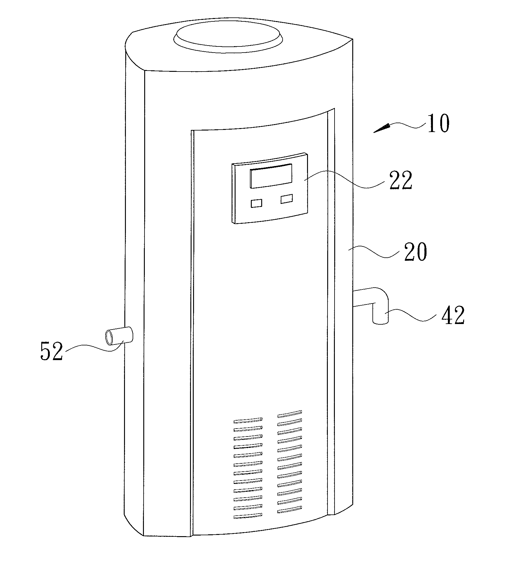
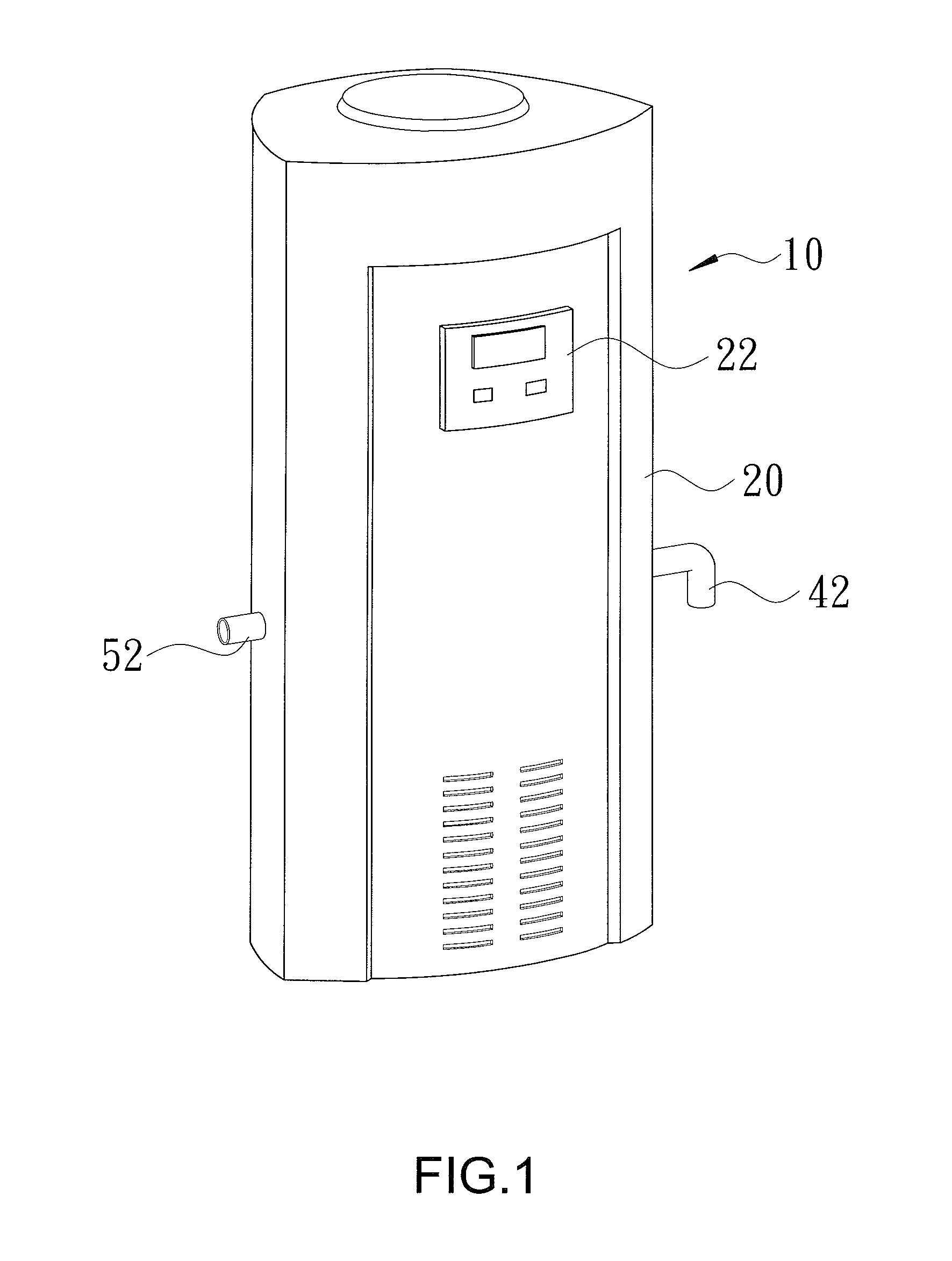
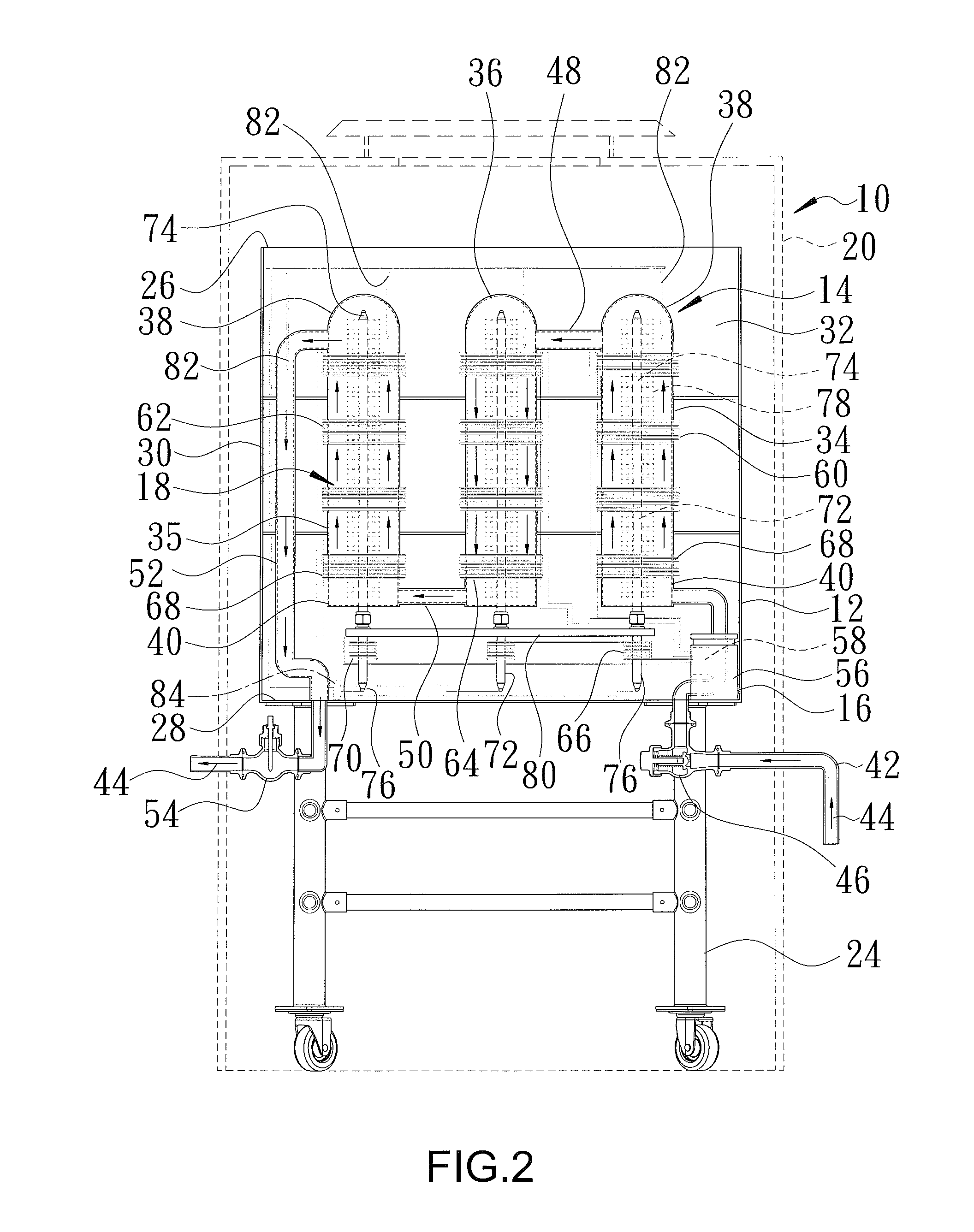
[0015]A high efficiency water boiling device of the present invention is shown in FIGS. 1 and 2 of the drawings and generally designated 10. The water boiling device 10 includes a machine body 12, a heat tank unit 14, a high frequency induction heater 16, and a heat pipe unit 18. The machine body 12 is received in an outer shell 20. On the outer shell 20, a man-machine interface (operation panel) 22 is provided for users to do settings and / or read the temperature of hot water. A support frame 24 is provided below the machine body 12 to support the machine body 12. In this embodiment, machine body 12 includes a top plate 26, a bottom plate 28, and a side plate 30 located between top plate 26 and bottom plate 28 and defining a periphery of machine body 12. The machine body 12 includes a receiving space 32 therein.

[0016]Heat tank unit 14 is received in the receiving space 32 of machine body 12 and includes a plurality of heating tanks spaced in a horizontal direction. In this embodimen...

second embodiment

[0023]Now that the basic teachings of the present invention have been explained, many extensions and variations will be obvious to one having ordinary skill in the art. FIG. 3 shows a water boiling device 10 of this invention. Description of the parts of water boiling device 10 shown in FIG. 3 identical to those shown in FIG. 2 is omitted. In particular, water boiling device 10 in this embodiment does not contain heat pipe unit 18 but only includes machine body 12, heat tank unit 14, and high frequency induction heater 16. Heat tank unit 14 includes a plurality of intermediate heating tanks 36 located between first and second heating tanks 34 and 35. In this embodiment, each heating tank 34, 35, 36 is a metallic tube and includes upper and lower ends 38, and 40 spaced in the vertical direction. Intermediate heating tanks 36 are spaced in the horizontal direction and connected to each other with pipes 86. Further, two of intermediate heating tanks 36 are respectively connected to fir...


PUM

PropertyMeasurementUnit
Flow rateaaaaaaaaaa
Frequencyaaaaaaaaaa

Abstract

A water boiling device includes a heat tank unit received in a machine body, a high frequency induction heater, and a heat pipe unit. Heat tank unit includes first and second heating tanks in communication with each other. Outside water can flow into first and second heating tanks. The high frequency induction heater includes a heat pipe induction coil and first and second induction coils. The heat pipe unit includes first and second heating pipes. An upper section of each heating pipe is received in one of heating tanks, and a lower section of each heating pipe extends out of heating tanks and is inserted into heat pipe induction coil. The first and second heating tanks will heat up to heat the water in first and second heating tanks when a high frequency current is passed through the heat pipe induction coil and first and second induction coils.

Description

BACKGROUND OF THE INVENTION[0001]1. Field of the Invention[0002]The present invention relates to a water boiling device and, more particularly, to a water boiling device by means of high-frequency heating.[0003]2. Description of the Related Art[0004]A water boiler operated on gas, natural gas or diesel is often used in a school, hospital, hotel, office, factory, military camp or the like to provide water for drinking or washing. However, there is always a risk of incomplete combustion that leads to the production of lethal carbon monoxide. Furthermore, if we use electric energy for the heating, there is the possibility of high power consumption and slow heating rate.[0005]Thus, a fast heating, energy saving, quite safe water boiler is required.BRIEF SUMMARY OF THE INVENTION[0006]Therefore, it is an objective of the present invention to overcome the aforementioned shortcoming and deficiency of the prior art by providing a water boiling device that utilizes high frequency induction he...

Claims


Application Information

Patent Timeline
IPC IPC(8): H05B6/10
CPCH05B6/108
Inventor YANG, SHUN-CHIYANG, MAO-HSIUNGYANG, TSUNG-CHUANWU, FANG-MINGWU, CHENG-YEN
Owner YANG SHUN CHI
Why Eureka
Try Eureka