
Piston type internal combustion engine

Inactive Publication Date: 2016-02-09
TAKAHARA NOBUYA
View PDF13 Cites 1 Cited by
  • Summary
  • Abstract
  • Description
  • Claims
  • Application Information

AI Technical Summary

Benefits of technology

The present invention provides an improved piston type internal combustion engine that moves smoothly in high-pressure, high-temperature gas and maximizes heat efficiency by reducing thermal loss. This is achieved by cooling only the driving portion of the piston, while the combustion chamber (power portion) is less likely cooled. The engine is superior in fuel economy, generates less CO2, is low in pump loss of the intake and exhaust valves, and low in cooling power, making it possible to reduce the size of the cooling device, compared to a conventional engine of the same output.

Problems solved by technology

By cooling the cylinder 1, thermal energy is lost during the combustion / expansion stroke, so that thermal efficiency deteriorates.
However, in the conventional arrangement, since the cylinder is a monolithic member, it is necessary to cool the entire cylinder 1, so that thermal efficiency is low.

Method used


Image

  • Piston type internal combustion engine
  • Piston type internal combustion engine
  • Piston type internal combustion engine

Examples


examples

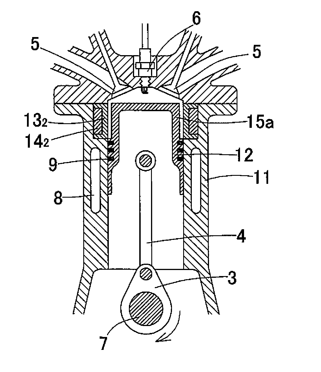
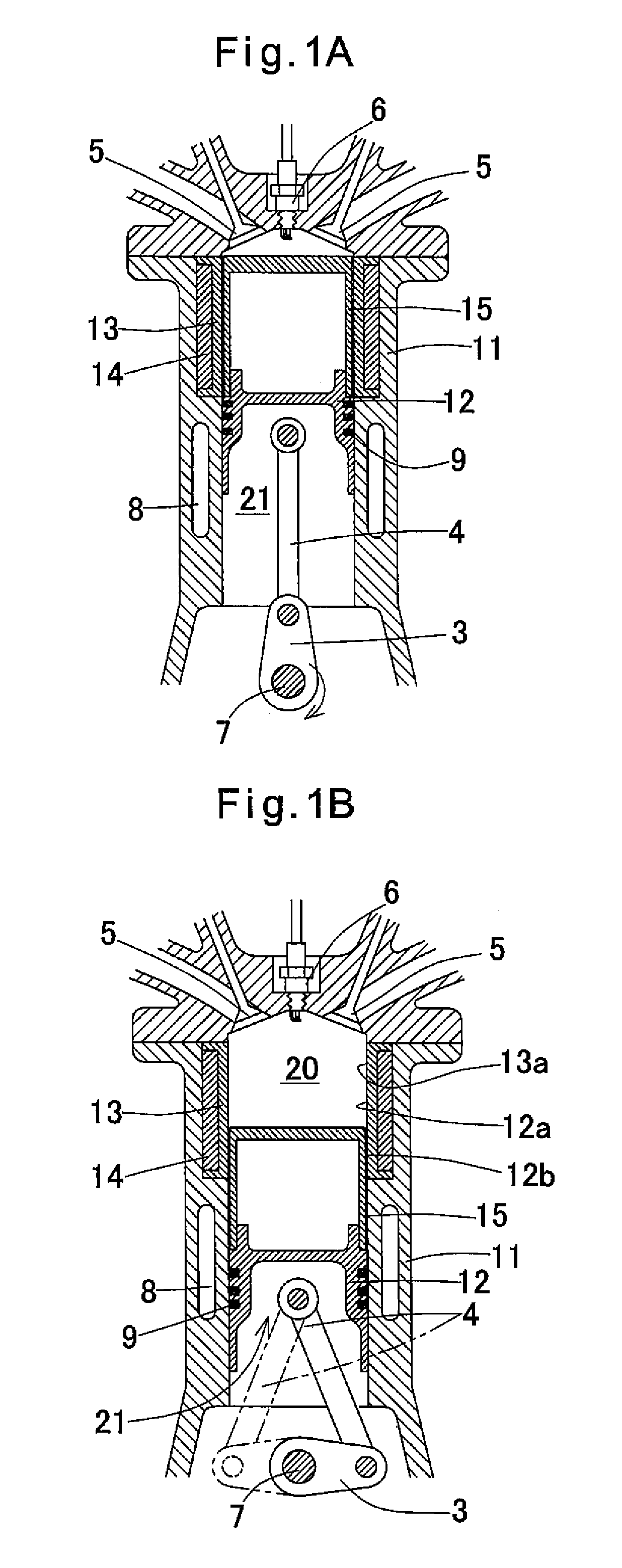
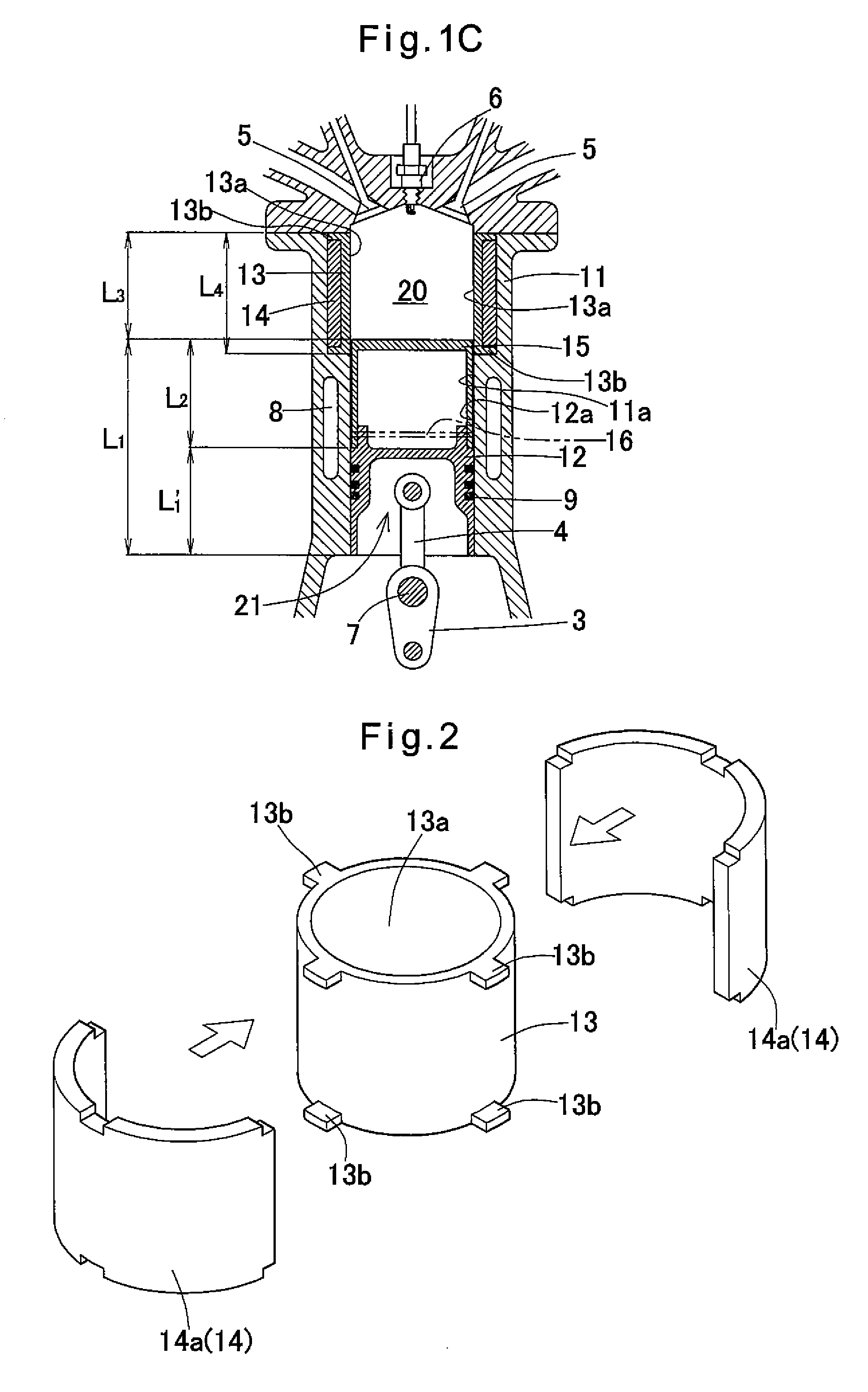
[0032]FIGS. 1A to 1C and 2 show an example of the present invention. Elements of these figures corresponding to those shown in FIGS. 4A to 4C are denoted by identical numerals. This example is described with reference to FIG. 1C, in which the piston 12 is at the lowermost position, in comparison with FIG. 4C, which shows a conventional engine. The piston 12 of the example has a length L1 which is larger than the length L1′ of the conventional piston 2 by the stroke length L2 (=S) of the piston 2 (L1=L1′+S). The cylinder 11 is correspondingly longer than the cylinder 1 by a length L3 (=S). The piston 12 has a longitudinally extended cylindrical portion 15 having such a diameter that a gap 12a is defined between the cylindrical portion 15 and the inner wall 11a of the cylinder 11. The size of the gap 12a is determined, e.g. by experiments, such that the cylindrical portion 15, at the top of the piston 12, does not come into sliding contact with the inner surface of the cylinder 11 and...


PUM


Abstract

An internal combustion engine includes a cylinder of which the interior is divided into two in the longitudinal direction. The lower chamber serves as a mechanical driving portion in which the piston is reciprocated. The upper chamber serves as a power portion in which combustion gas is drawn in, compressed, burned and exhausted. A cylindrical portion with a lid which moves into the power portion is continuously provided on top of the piston. A gap is defined between the cylindrical portion and the inner peripheral surface of the power portion of the cylinder. The inner peripheral surface of the power portion is defined by a heat shield tube fitted in the cylinder. A heat insulating tube is provided on the outer periphery of the heat shield tube.

Description

[0001]This application is based on and claims priority under 35 U.S.C. sctn. 119 with respect to Japanese Patent Application No. 2014-31357 filed on Feb. 21, 2014, the entire content of which is incorporated herein by reference.FIELD OF THE INVENTION[0002]This invention relates to a piston type internal combustion engine having high thermal efficiency.BACKGROUND OF THE INVENTION[0003]A typical piston type internal combustion engine (reciprocating engine) is described first. FIGS. 4A to 4C show a four-cycle internal combustion engine, which typically includes a cylinder 1 (defining a cylinder bore), a piston 2 slidably mounted in the cylinder bore of the cylinder 1, and a connecting rod 4 through which the piston 2 is connected to a crankshaft 3. This engine further includes intake and exhaust valves 5, and a spark plug 6.[0004]This internal combustion engine is configured such that when the piston 2 moves down from the uppermost position (FIG. 4A) to an intermediate position (FIG. 4...

Claims


Application Information

Patent Timeline
IPC IPC(8): F02B75/08F02F1/00F01B7/18F02F1/18
CPCF02F1/004F01B7/18F02F1/18F05C2251/048Y02T10/125Y02T10/12
Inventor TAKAHARA, NOBUYA
Owner TAKAHARA NOBUYA
Learn More