Surface light source device and frame used therein

a technology of surface light source and light source device, which is applied in the direction of lighting and heating apparatus, mechanical equipment, instruments, etc., can solve the problems of frame breaking and other problems, and achieve the effects of enhancing emission luminance, improving light efficiency of surface light source device, and reducing visual quality

Inactive Publication Date: 2012-03-15
ORMON CORP
View PDF12 Cites 50 Cited by
  • Summary
  • Abstract
  • Description
  • Claims
  • Application Information

AI Technical Summary

Benefits of technology

[0027]In the frame according to one or more embodiments of the invention, the inner peripheral surface of at least one side of the frame includes the first frame portion made of the light-reflecting material such as the white resin, so that the light that leaks from the outer peripheral surface of the lightguide plate can be reflected and incident to the lightguide plate again by the first frame portion in the side when accommodated in the surface light source device. Therefore, the use efficiency of the light of the surface light source device can be improved to enhance the emission luminance. Additionally, in the frame according to one or more embodiments of the invention, the outer peripheral surface of the first frame portion is covered with the second frame portion made of the light-absorbing material such as the black resin, so that the light transmitted through the first frame portion can be absorbed by the second frame portion to hardly leak to the outside of the frame. Therefore, the degradation of the ...

Problems solved by technology

On the other hand, in the case in which the first frame portion and the second frame portion are separately molded, it is necessary to assemble the first frame p...

Method used


Image

  • Surface light source device and frame used therein
  • Surface light source device and frame used therein
  • Surface light source device and frame used therein

Examples


first embodiment

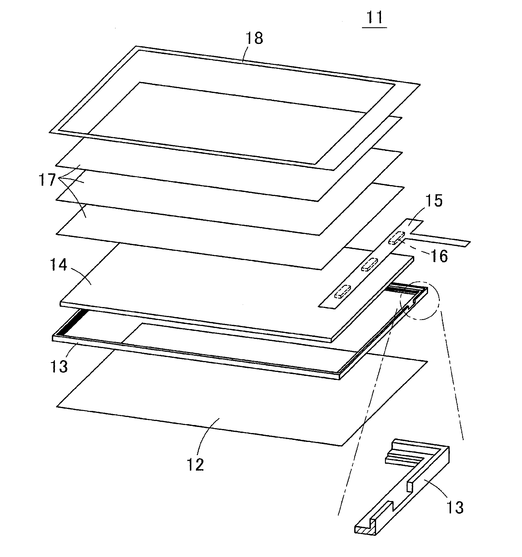
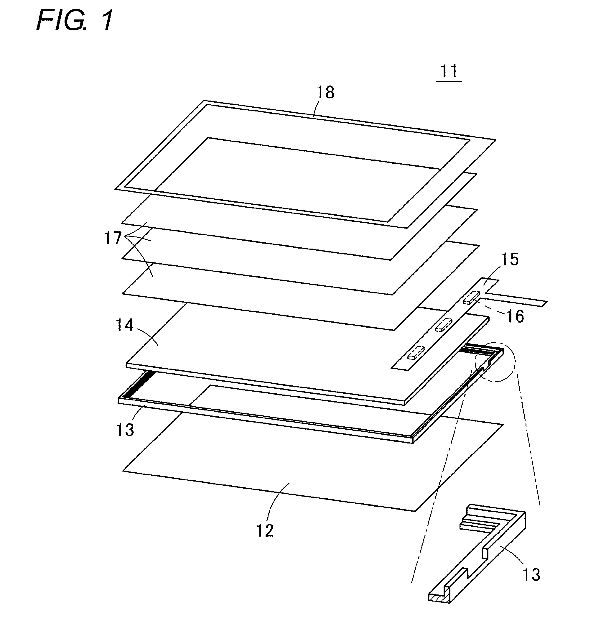
[0049]FIG. 3 is an exploded perspective view illustrating a surface light source device 21 according to a first embodiment of the invention. The surface light source device 21 includes a reflecting sheet 22, a frame 23, a lightguide plate 24, plural light sources 26 mounted on a lower surface of flexible printed board 25, a diffusion sheet 27a, prism sheets 27b and 27c (sometimes the diffusion sheet 27a and the prism sheets 27b and 27c are collectively referred to as an optical sheet), and a light shielding sheet 28.

[0050]The reflecting sheet 22 is a flat sheet made of a white resin sheet or a metallic foil, which has a high reflectance.

[0051]The flexible printed board 25 includes a light source mounting portion 25a on which the light source 26 is mounted and a lead portion 25b that connects the light source mounting portion 25a to an external circuit (power supply circuit). The lead portion 25b is drawn from the light source mounting portion 25a. The plural light sources 26 are mou...

second embodiment

[0077]FIG. 9 is an enlarged sectional view illustrating part of a surface light source device 81 according to a second embodiment of the invention. In the surface light source device 21 of the first embodiment, the bonded surface 23c between the inside frame portion 23a and the outside frame portion 23b is perpendicular to the lower surface of the frame 23. On the other hand, in the surface light source device 81 of the second embodiment, the bonded surface 23c between the inside frame portion 23a and the outside frame portion 23b is inclined with respect to the surface perpendicular to the lower surface of the frame 23. In FIG. 9, the bonded surface 23c is inclined such that the inside frame portion 23a is thickened upward or such that the outside frame portion 23b is thinned upward. Alternatively, the bonded surface 23c may be inclined such that the inside frame portion 23a is thinned upward or such that the outside frame portion 23b is thickened upward. According to one or more e...

third embodiment

[0080]FIG. 10A is an enlarged sectional view illustrating part of a surface light source device 82 according to a third embodiment of the invention. In the third embodiment, the rib 44 of the outside frame portion 23b is eliminated to flatten the upper surface 43 of the outside frame portion 23b. According to the third embodiment, the surface light source device 82 expands in application because a size of the liquid crystal panel is not restricted by the rib 44.

[0081]As illustrated in the surface light source device 83 of FIG. 10B, the rib 44 of the outside frame portion 23b may be eliminated in the frame 23 having the inclined bonded surface 23c.


PUM


Abstract

Light that leaks from an outer peripheral surface of a lightguide plate can be reflected and returned to the lightguide plate by a frame, and light that is transmitted through the frame to leak out can be reduced. A reflecting sheet is disposed in a lower surface of the frame, and the lightguide plate and the light source are accommodated in the frame. The frame is formed such that an outer peripheral surface of a rectangular-frame-shaped inside frame portion made of a white resin is covered with a rectangular-frame-shaped outside frame portion made of a black resin. The inside frame portion and the outside frame portion are integrally molded by a two-color molding method.

Description

BACKGROUND OF THE INVENTION[0001]1. Technical Field[0002]The present invention relates to a surface light source device and a frame used therein. For example, the invention relates to a surface light source device that is used as a backlight illuminating a liquid crystal panel, and to a frame that surrounds a lightguide plate in the surface light source device.[0003]2. Related Art[0004][First Conventional Example][0005]A liquid crystal display unit of a mobile phone is configured such that a surface light source device (backlight) for illumination is disposed behind a liquid crystal panel. FIG. 1 is an exploded perspective view illustrating a general structure of a surface light source device used in the liquid crystal display unit. FIG. 2A is a plan view of the assembled surface light source device, and FIG. 2B is an enlarged sectional view taken on a line X-X of FIG. 2A.[0006]As illustrated in FIGS. 1, 2A, and 2B, in a surface light source device 11, a reflecting sheet 12 is bonde...

Claims


Application Information

Patent Timeline
IPC IPC(8): F21V7/04F21V8/00
CPCG02B6/0031G02B6/0065G02F1/133308G02B6/0083G02B6/0088G02B6/0068
Inventor OZAWA, KENJINAMBU, KENSUKEHIRAKI, YUICHI
Owner ORMON CORP
Why Eureka
Try Eureka