Power transmitter and wireless power transmission system

a wireless power transmission and transmitter technology, applied in the direction of digital transmission, loudspeakers, pulse techniques, etc., can solve the problems of battery replacement or charging, deterioration of the appearance low installation freedom of the audio device, so as to achieve stable wireless power transmission

Active Publication Date: 2012-03-15
PANASONIC INTELLECTUAL PROPERTY MANAGEMENT CO LTD
View PDF14 Cites 123 Cited by
  • Summary
  • Abstract
  • Description
  • Claims
  • Application Information

AI Technical Summary

Benefits of technology

[0035]According to the present invention, stable wireless power transmission ca...

Problems solved by technology

This lowers the freedom of installation of the audio device and also deteriorates the appearance of the audio device.
In the case where a battery is built in, there is a problem that each time the battery is consumed, the battery needs to be exchanged or charged.
Namely, there is a problem that the volume of the audio signal reproduced from the speaker is changed depending on whether a request signal is received or not.
This problem occurs in wireless power transmission systems for transmitting an audio signal to a speaker and also in oth...

Method used


Image

  • Power transmitter and wireless power transmission system
  • Power transmitter and wireless power transmission system
  • Power transmitter and wireless power transmission system

Examples


embodiment 1

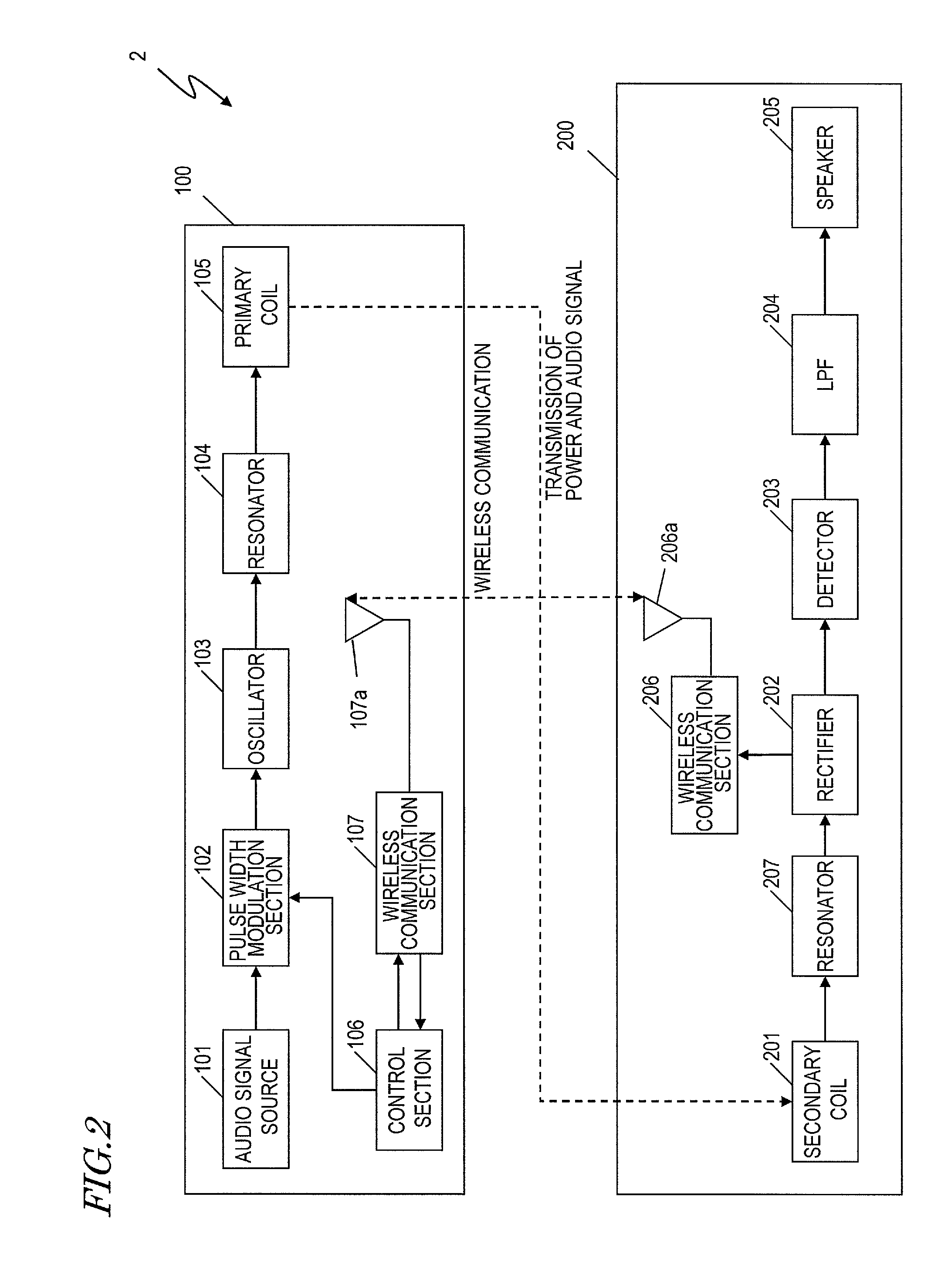
[0063]First, Embodiment 1 According to the Present invention will be described.

[0064]FIG. 2 is a block diagram showing a structure of a wireless power transmission system 2 in this embodiment. The wireless power transmission system 2 includes a power transmitter 100 and a power receiver 200.

[0065]The power transmitter 100 includes an audio signal source 101, a pulse width modulation section 102, an oscillator 103, a resonator 104, a primary coil 105, a control section 106, and a wireless communication section 107. The power receiver 200 includes a secondary coil 201, a resonator 207, a rectifier 202, a detector 203, a low pass filter (LPF) 204, a speaker 205, and a wireless communication section 206. Although not shown in FIG. 2, the power transmitter 100 is supplied with power from an AC power supply, from a DC power supply such as a battery or the like, or by wireless power transmission from another wireless power transmission system not shown. In this embodiment, the pulse width ...

embodiment 2

[0143]Now, Embodiment 2 according to the present invention will be described.

[0144]The wireless power transmission system 2 in Embodiment 1 transmits power and an audio signal in superposition on the power, and reproduces sound from the speaker 205. By contrast, a wireless power transmission system in this embodiment transmits only power with no audio signal being transmitted, and supplies the power to a load device on the power receiver side. Hereinafter, a structure of the wireless power transmission system for transmitting only power will be described with reference to the drawings. The elements which have been described above are represented by identical reference numerals to those used above and descriptions thereof will be omitted.

[0145]FIG. 9 shows a structure of a wireless power transmission system 3 in this embodiment. The wireless power transmission system 3 includes a power transmitter 300 and a power receiver 400. The transmission 300 includes a power source 301, a pulse...

embodiment 3

[0184]Now, Embodiment 3 according to the present invention will be described.

[0185]The wireless power transmission system 2 in Embodiment 1 changes the amplitude of the triangular wave used at the time of pulse width modulation performed on an audio signal, so that the volume of the sound reproduced from the speaker 205 is kept constant regardless of whether the wireless communication is being performed or not. By contrast, in this embodiment, the sampling cycle, not the amplitude of the triangular wave, is changed, so that the volume of the sound reproduced from the speaker 205 is kept constant regardless of whether the wireless communication is being performed or not. Hereinafter, a structure of a wireless power transmission system in this embodiment will be described with reference to the drawings. The elements which have been described above are represented by identical reference numerals to those used above and descriptions thereof will be omitted.

[0186]FIG. 14 is a block diagr...


PUM


Abstract

A power transmitter 50 is usable in a wireless power transmission system for transmitting power wirelessly. The power transmitter 50 includes a power transmitting section 51 for transmitting power; a communication section 52 for communicating information, for controlling the transmission of the power, with the power receiver 60; and a control section 53 for controlling the power transmitting section 51 such that the power to be sent out by the power transmitting section 51 is higher while the communication section 52 is performing the communication.

Description

BACKGROUND OF THE INVENTION[0001]1. Field of the Invention[0002]The present invention relates to a power transmitter and a wireless power transmission system for transmitting power wirelessly.[0003]2. Description of the Related Art[0004]In a conventional audio device, an audio signal source for generating an audio signal and a speaker for converting the audio signal, which is an electric signal, into vibration of air and reproducing the vibration of air as a sonic wave are connected to each other via a cable, and the audio signal is transmitted to the speaker via the cable. However, it is occasionally desirable not to use the cable which connects the audio signal source and the speaker for various reasons such as the installation environment, convenience, appearance and the like of the audio device. In order to respond to such a demand, there are wireless speaker devices for transmitting an audio signal generated by the audio signal source to the speaker wirelessly using wireless co...

Claims


Application Information

Patent Timeline
IPC IPC(8): H04L27/00H03K7/08H04B1/04H04B1/16
CPCH04B5/0006H04B5/0037H04B5/0093H04R2420/07H02J17/00H04R2201/028H02J5/005H02J50/12H02J50/80
Inventor OKAMURA, SHUTAIKINOSHITA, KEISUKEKAWAMURA, JUNICHI
Owner PANASONIC INTELLECTUAL PROPERTY MANAGEMENT CO LTD
Why Eureka
Try Eureka