Hydraulic controller of power transmission device

a technology of power transmission device and hydraulic controller, which is applied in the direction of fluid gearing, mechanical equipment, gearing, etc., can solve the problems of transmission shock and load given to the transmission, and achieve the effects of lessening the hydraulic pressure, preventing slippage and transmission shock

Active Publication Date: 2006-07-11
HONDA MOTOR CO LTD
View PDF5 Cites 4 Cited by
  • Summary
  • Abstract
  • Description
  • Claims
  • Application Information

AI Technical Summary

Benefits of technology

[0011]In accordance with the first aspect of the present invention, because when controlling the direct coupling mechanism by the solenoid valve, the hydraulic controller of the power transmission device comprises the change-over element for changing over the hydraulic pressure supplied to the forward / backward change-over mechanism so as to become the low pressure at the time of the deceleration driving, the hydraulic controller of the power transmission device can lessen the hydraulic pressure supplied to the forward / backward change-over mechanism. Therefore, the forward / backward change-over mechanism can loosen an engagement state. Then, for example, when a strong braking is implemented during an engine brake, a load is given to the transmission due to a transmission shock. Because the hydraulic pressure supplied to the forward / backward change-over mechanism is lessened and thereby a forward clutch of the forward / backward change-over mechanism slips, the load can alleviate a load of a V belt. Therefore, the V belt is prevented from being damaged due to the load and thus can be protected. In addition, any of forward clutch and backward brake f of the forward / backward change-over mechanism is engaged in a loose state and slips, thereby the slip and transmission shock of the transmission are prevented, and the power transmission of the motor can be made smoother by the slip. Accordingly, the load on the V belt is reduced and a life thereof can be made longer.

Problems solved by technology

Then, for example, when a strong braking is implemented during an engine brake, a load is given to the transmission due to a transmission shock.

Method used


Image

  • Hydraulic controller of power transmission device
  • Hydraulic controller of power transmission device
  • Hydraulic controller of power transmission device

Examples


Embodiment Construction

[0018]First will be described a hydraulic controller of a power transmission device related to an embodiment of the present invention, referring to FIGS. 1 to 6.

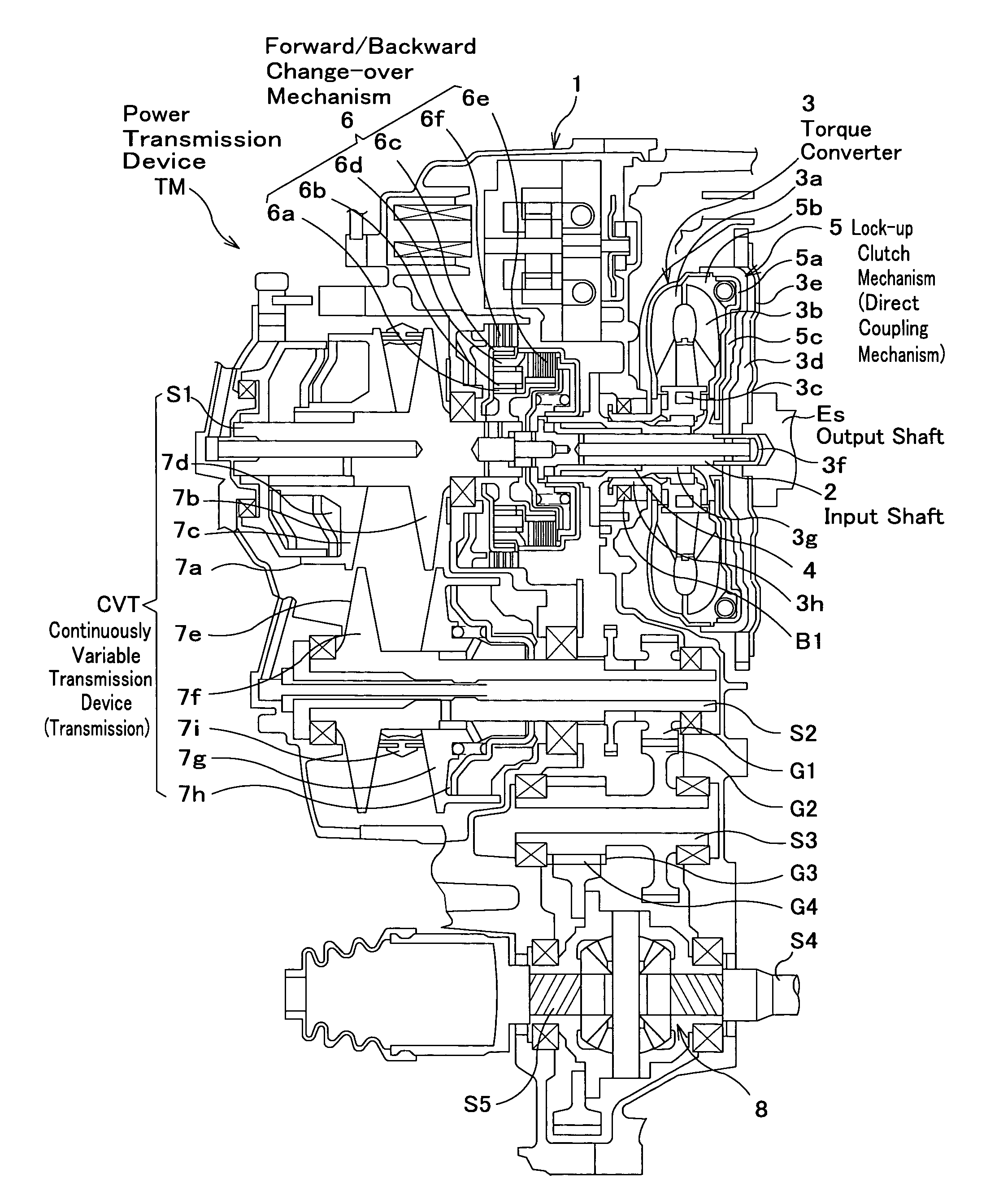
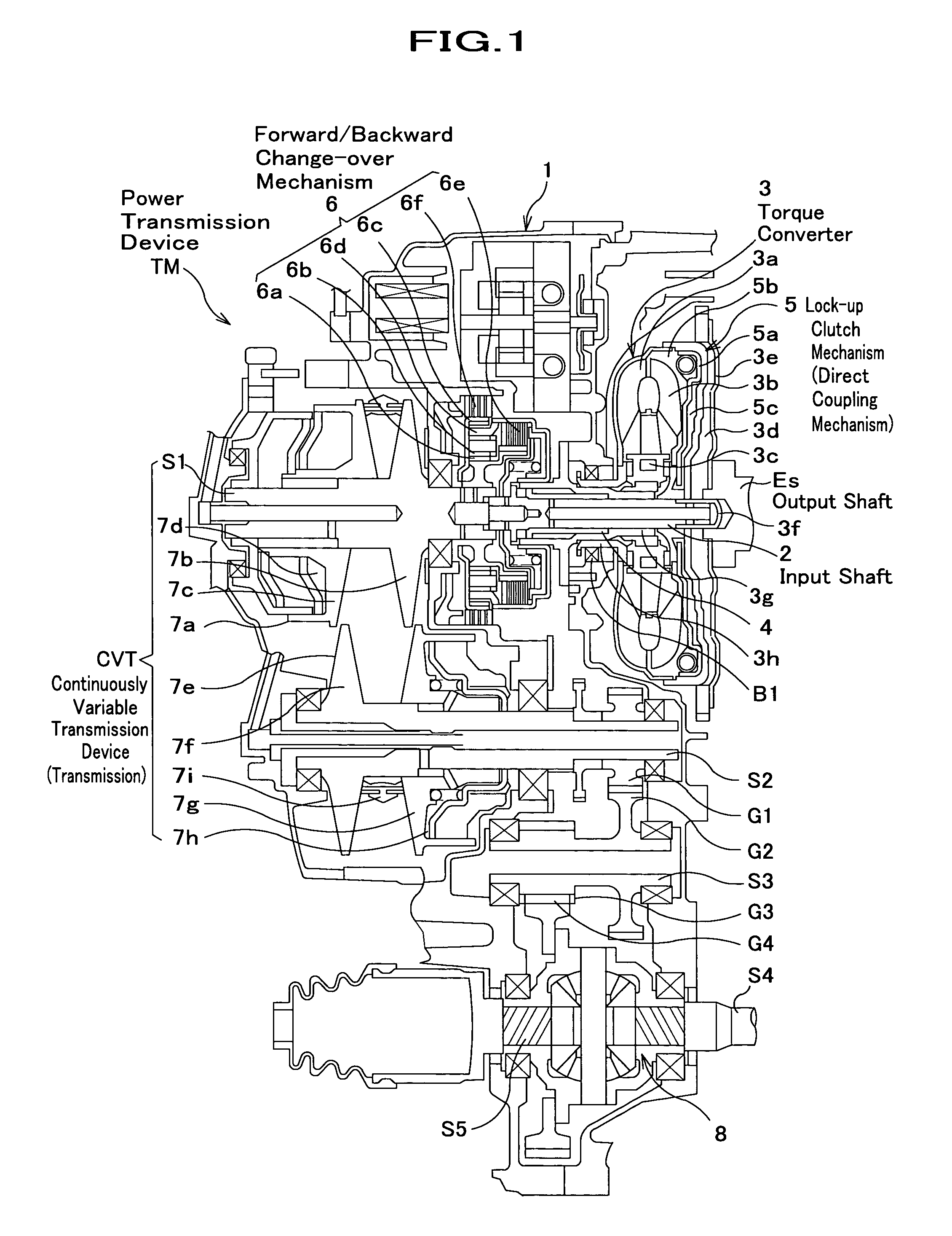
[0019]As shown in FIG. 1, a power transmission device TM comprises a continuously variable transmission device CVT for changing a rotation speed, which is input from an output shaft Es of an engine (not shown), and outputting it; and a torque converter 3, which is provided between the engine (not shown) and the continuously variable transmission device CVT, for transmitting the motor power. In the power transmission device TM the torque converter 3 and a forward / backward change-over mechanism 6 are placed in parallel on a primary shaft S1 within a transmission case 1.

[0020]The continuously variable transmission device CVT described later is housed within the transmission case 1 and freely rotatably supported by an input shaft 2, the primary shaft S1, a secondary shaft S2, a counter shaft S3, and bearings whose respective lef...


PUM


Abstract

A hydraulic controller of a power transmission device is equipped with a transmission for changing a rotation speed of motor power input from a motor and outputting the motor power; a forward / backward change-over mechanism provided between an input shaft, where the motor power of the motor is input and the transmission; and a torque converter having a direct coupling mechanism for transmitting the motor power between an output shaft and the input shaft of the motor; a solenoid valve for adjusting an original pressure and generating a control pressure; and a change-over element for changing over a hydraulic pressure supplied to the forward / backward change-over mechanism so as to become a low pressure during deceleration driving when the direct coupling mechanism is controlled by the solenoid valve, wherein any one of engagement states of the forward / backward change-over mechanism and the direct coupling mechanism is controlled by the control pressure.

Description

BACKGROUND OF THE INVENTION[0001]1. Field of the Invention[0002]The present invention relates to a hydraulic controller of a power transmission device mounted on an automobile.[0003]2. Description of the Related Art[0004]Conventionally, a power transmission device mounted on an automobile transmits motor power of a motor, which is input, for example, through a torque converter, to drive wheels through a forward / backward change-over mechanism and a belt type continuously variable transmission. In such the power transmission device it is necessary to control an engagement capacity of friction engagement elements (a clutch for a forward move and a brake for a backward move (hereinafter simply referred to as “forward clutch” and “backward brake,” respectively) for configuring the forward / backward change-over mechanism in order to prevent an excessive torque from being input to a V belt; alleviate a transmission shock generated at the time of a start from a neutral, a forward / backward ch...

Claims


Application Information

Patent Timeline
Patent Type & Authority Patents(United States)
IPC IPC(8): F16H47/08F16D48/02F16H61/02F16H61/14F16H61/662
CPCF16H61/0204F16H61/143Y10T477/6217F16H2061/6608F16H61/66272
Inventor ISHIKAWA, TOMOAKINAKANO, SHIGEJIFUJISHIMA, KAZUNORIYAMAGUCHI, MASAAKIFUJITA, TSUYOSHIUENO, TAKAO
Owner HONDA MOTOR CO LTD
Why Eureka
Try Eureka