Vehicle braking system

a technology for braking systems and vehicles, applied in the direction of fluid couplings, rotary clutches, servomotors, etc., can solve the problems of increasing the hydraulic pressure of the boosted hydraulic pressure chamber to speed up the movement of the backup piston, not only complicating the configuration, but also increasing the number of parts. , to achieve the effect of reducing the number of parts and simplifying the configuration

Inactive Publication Date: 2006-09-12
AUTOLIV NISSIN BRAKE SYST JAPAN CO LTD +1
View PDF11 Cites 9 Cited by
  • Summary
  • Abstract
  • Description
  • Claims
  • Application Information

AI Technical Summary

Benefits of technology

[0007]The present invention has been made in view of the above circumstances and has an object to provide a vehicle braking system which can avoid increase in the hydraulic pressure of a boosted hydraulic pressure chamber during forward movement of a backup piston, using a simple configuration with a reduced number of parts.
[0009]With the configuration of the first feature, since reduction in the hydraulic pressure of the input chamber, i.e., reduction in the hydraulic pressure of the hydraulic power source, causes reduction in the hydraulic force which presses the backup piston toward the backward limit, it is possible to advance the backup piston according to operation of the brake pedal, abut against the pusher in the front part of the backup piston against the master piston with a clearance provided between the casing and the inner contact surface of the master piston to advance the master piston in this state, thereby applying brake hydraulic pressure to the wheel brakes from the master cylinder. When the backup piston and master piston move forward in this way, there is no increase in the hydraulic pressure of the boosted hydraulic pressure chamber, because the piston body of the backup piston is substantially equal in seal diameter to the master piston, because the amount of volume increased in the boosted hydraulic pressure chamber is substantially equal to the amount of volume decreased in the input chamber when the pusher of the backup piston pushes the master piston in the forward direction, and because the boosted hydraulic pressure chamber is communicated with the input chamber via the pressure regulating means. Thus, it is possible to avoid increase in the hydraulic pressure of the boosted hydraulic pressure chamber during forward movement of the backup piston, using a simple configuration with a reduced number of parts, without need for any emergency control valve conventionally required.
[0011]According to a third feature of the present invention, in addition to the configuration of the second feature, the combined force of backward hydraulic pressure which acts on the backup piston as the output hydraulic pressure of the hydraulic power source acts on the input chamber and spring force of the spring-urging means which urges the backup piston in the backward direction is set at 300 to 1000 N. With this configuration, by urging the backup piston in the backward direction with a force of 300 N or more, it is possible to urge the backup piston reliably in the backward direction taking into consideration the output hydraulic pressure of the hydraulic power source and sliding resistance of the backup piston. Also, by urging the backup piston in the backward direction with a force of 1000 N or less, it is possible to prevent the master piston from being pushed into the master cylinder.
[0014]According to a fifth feature of the present invention, in addition to the configuration of the first feature, a normally closed pressure-reducing linear solenoid valve for regeneration and coordination is interposed between the boosted hydraulic pressure chamber and the reservoir, while a normally open pressurizing linear solenoid valve for regeneration and coordination and a second one-way valve are interposed between the output chamber and the boosted hydraulic pressure chamber, where the second one-way valve is connected in parallel to the pressurizing linear solenoid valve for regeneration and coordination to allow the brake fluid to flow from the boosted hydraulic pressure chamber to the output chamber.

Problems solved by technology

Consequently, when the hydraulic pressure of a boosted hydraulic pressure chamber decreases due to a defect of a hydraulic power source, if the backup piston moves forward in response to operation of a brake operating member, the amount of volume decreased in the boosted hydraulic pressure chamber caused by the forward movement of the backup piston will exceed the amount of volume increased in the boosted hydraulic pressure chamber caused by the forward movement of the master piston, resulting in increase in the hydraulic pressure of the boosted hydraulic pressure chamber to speed up the movement of the backup piston if no measure is taken.
This not only complicates the configuration, but also increases the number of parts.

Method used


Image

  • Vehicle braking system
  • Vehicle braking system
  • Vehicle braking system

Examples


first embodiment

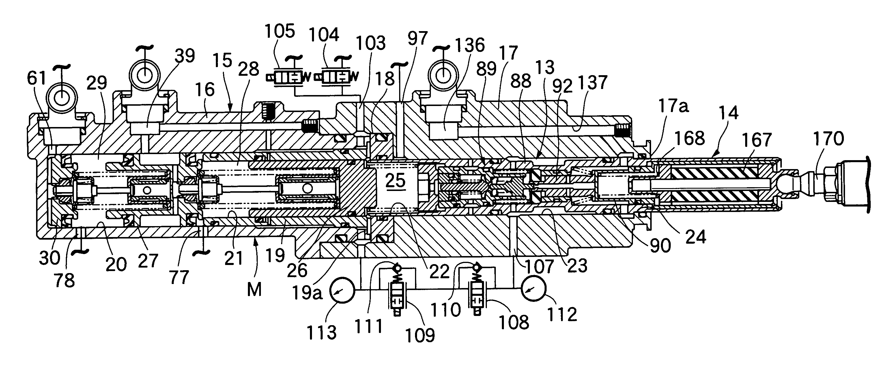
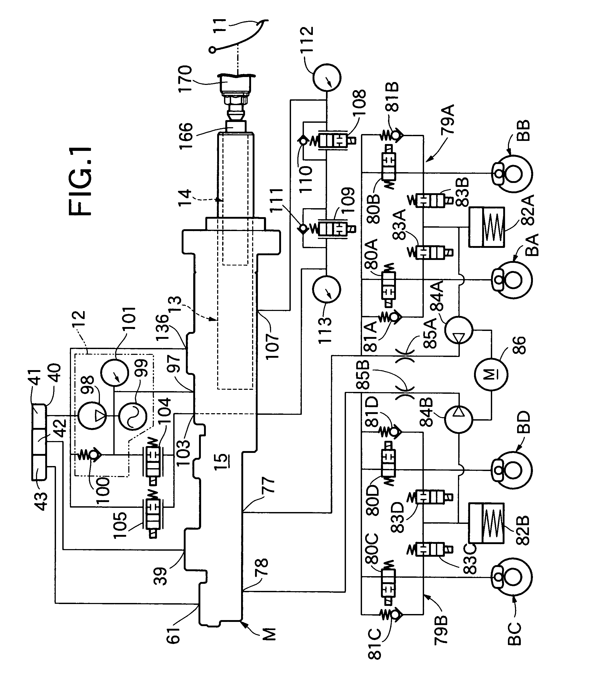
[0026]the present invention will be described with reference to FIGS. 1 to 8. Referring first to FIG. 1, a braking system for a four-wheeled vehicle comprises: a tandem master cylinder M; a hydraulic booster 13 which regulates hydraulic pressure of a hydraulic power source 12 according to a brake operating force inputted from a brake pedal 11 serving as a brake operating member, and which applies the hydraulic pressure to the master cylinder M; and a brake stroke simulator 14 interposed between the brake pedal 11 and hydraulic booster 13.

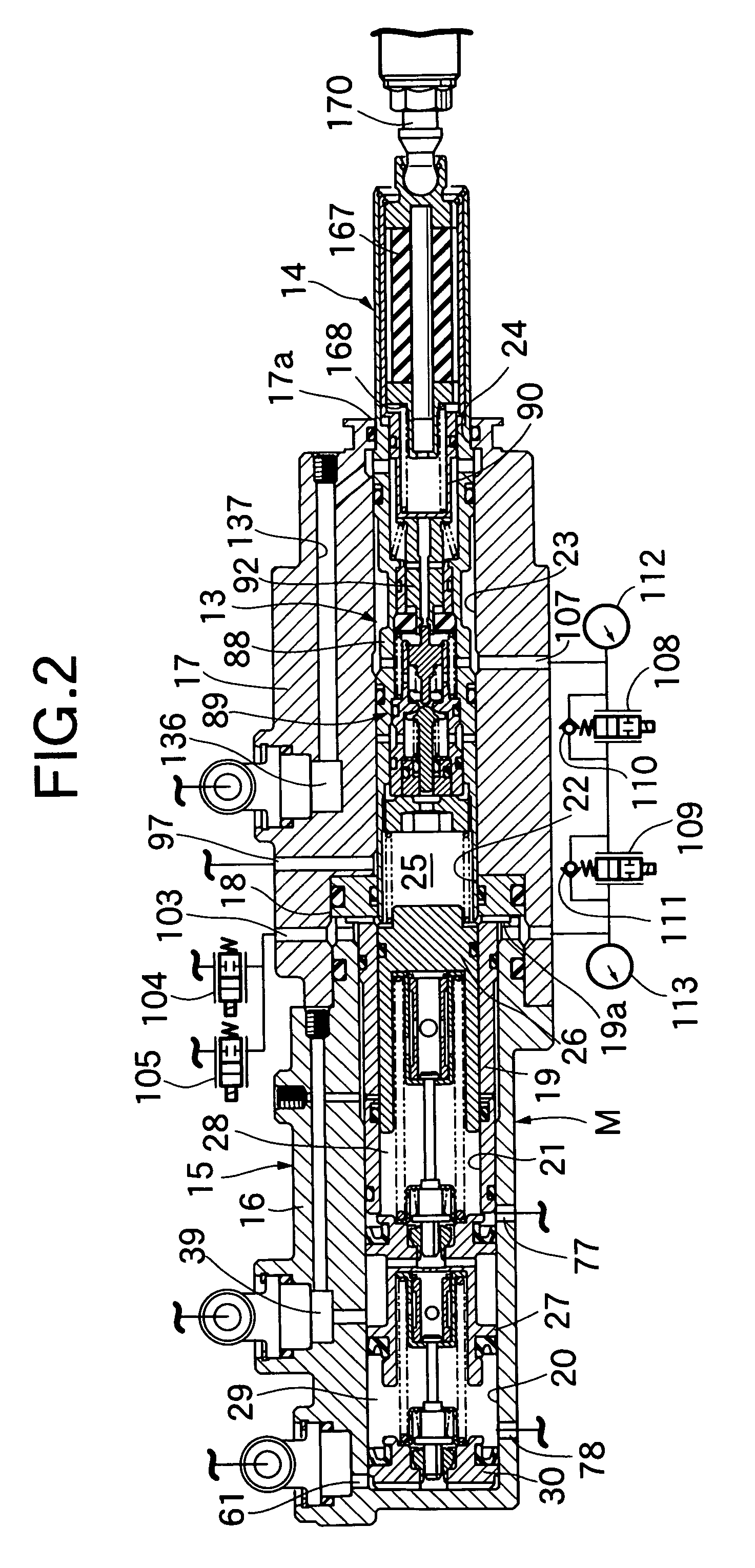
[0027]Referring also to FIG. 2, a casing 15 common to the master cylinder M and hydraulic booster 13 houses a first cylinder body 16 of a bottomed cylindrical shape with its front end closed; a second cylinder body 17 which is cylindrical in shape, has an inward flange 17a on its rear end, and is coupled coaxially with the rear part of the first cylinder body 16; a ring-shaped separator 18 sandwiched between the first and second cylinder bodies 16 a...


PUM


Abstract

In a vehicle braking system, a backup piston pushes a master piston directly from behind when hydraulic pressure of a boosted hydraulic pressure chamber decreases. The backup piston has a piston body which is slidably fitted in a casing, and a pusher which is slidably fitted in the casing with a seal diameter smaller than seal diameters of the master piston and the piston body and which extends to the front end of the piston body, to push the master piston from behind. An annular input chamber communicated with a hydraulic power source is formed between the backup piston and the casing. When the pusher pushes the master piston forward, amount of volume increased in the boosted hydraulic pressure chamber is set to be substantially equal to amount of volume decreased in the input chamber. Thus, it is possible to avoid increase in the hydraulic pressure of the boosted hydraulic pressure chamber during forward movement of the backup piston, using a simple configuration with a reduced number of parts.

Description

RELATED APPLICATION DATA[0001]The Japanese priority application No. 2003-406913 upon which the present application is based is hereby incorporated in its entirety herein by reference.BACKGROUND OF THE INVENTION[0002]1. Field of the Invention[0003]The present invention relates to a vehicle braking system comprising: a master cylinder in which a master piston with its back turned to a boosted hydraulic pressure chamber is slidably housed in a casing; a backup piston which is slidably housed in the casing with its front face turned to the boosted hydraulic pressure chamber and with its backward limit fixed, to push the master piston directly from behind in response to operation of a brake operating member when the hydraulic pressure of the boosted hydraulic pressure chamber decreases; and pressure regulating means which applies output hydraulic pressure of a hydraulic power source to the boosted hydraulic pressure chamber after regulating the output hydraulic pressure according to brak...

Claims


Application Information

Patent Timeline
Patent Type & Authority Patents(United States)
IPC IPC(8): B60T13/14B60T11/20B60T13/12B60T11/16
CPCB60T11/16B60T13/147B60T13/145
Inventor MATSUNO, ISAOTAGATA, KAZUHIROAOKI, YASUSHISUZUKI, KENJI
Owner AUTOLIV NISSIN BRAKE SYST JAPAN CO LTD
Why Eureka
Try Eureka