
Fluid pump control system for excavators

Inactive Publication Date: 2006-07-06
DOOSAN INFRACORE CO LTD
View PDF11 Cites 10 Cited by
  • Summary
  • Abstract
  • Description
  • Claims
  • Application Information

AI Technical Summary

Benefits of technology

[0013] Taking into account the afore-mentioned and other problems inherent in the prior art fluid pump control systems, it is an object of the present invention to provide a fluid pump control system for excavators that can acquire a positive fluid quantity control signal corresponding to the total sum of pilot signal pressures generated by remote control valves and, in proportion to magnitude of the positive fluid quantity control signal thus acquired, enables fluid pumps to produce hydraulic flows of a quantity great enough to actuate hydraulic actuators for smooth composite operations.
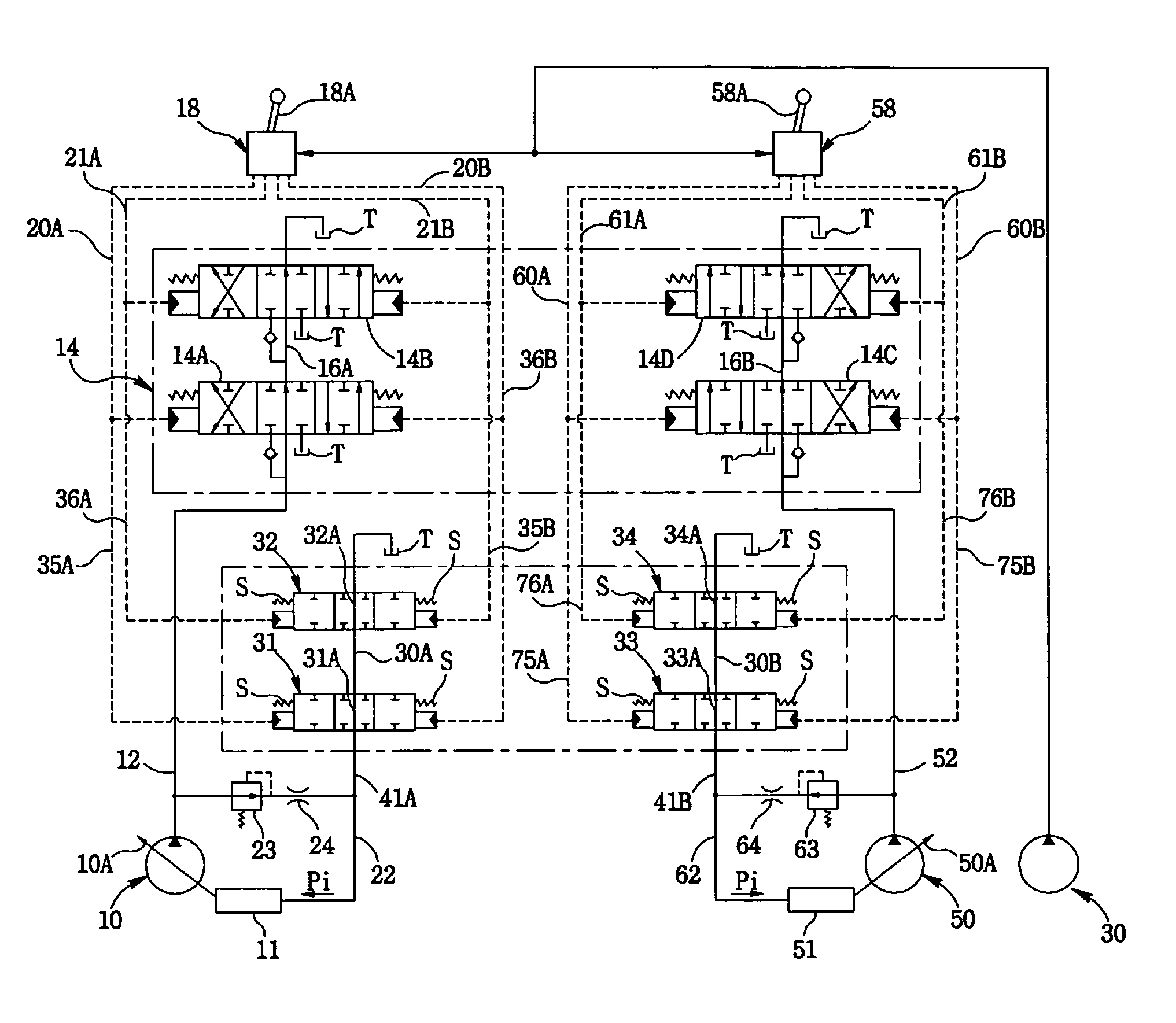
[0014] With this object in mind, one aspect of the present invention is directed to a fluid pump control system for excavators, comprising: at least one variable displacement fluid pump and a pilot pump each for producing a hydraulic flow; fluid quantity control mechanisms for controlling the discharge quantity of the respective fluid pumps; a control valve having a plurality of spools for controlling the hydraulic flow produced by the fluid pump and supplied to a plurality of hydraulic actuators through main fluid lines; remote control valves for reducing the pressure of the hydraulic flow produced by the pilot pump in proportion to manipulation amounts of control levers and for applying pilot signal pressures to the control valve through pilot signal lines to thereby shift the spools in one direction; fluid quantity control signal lines respectively bifurcated from the main fluid lines and connected to the fluid quantity control mechanisms in such a manner that the hydraulic flows in the main fluid lines can apply fluid quantity control signal pressures to the fluid quantity control mechanisms; signal pressure control lines for bringing the fluid quantity control signal lines into connection with a fluid tank to drop the fluid quantity control signal pressures within the fluid quantity control signal lines; and a plurality of cutoff valves attached to the signal pressure control lines in tandem and shiftable in concert with the shifting movement of the spools of the control valve for increasing the fluid quantity control signal pressures within the signal pressure control lines in proportion to the shifting amounts of the cutoff valves.
[0017] Another aspect of the present invention is directed to a fluid pump control system for excavators, comprising: at least one variable displacement fluid pump and a pilot pump each for producing a hydraulic flow; fluid quantity control mechanisms for controlling the discharge quantity of the respective fluid pumps; a control valve having a plurality of spools for controlling the hydraulic flow produced by the fluid pump and supplied to a plurality of hydraulic actuators through main fluid lines; remote control valves for reducing the pressure of the hydraulic flow produced by the pilot pump in proportion to manipulation amounts of control levers and for applying pilot signal pressures to the control valve through pilot signal lines to thereby shift the spools in one direction; at least one auxiliary pump for creating and applying fluid quantity control signal pressures to the fluid quantity control mechanisms; fluid quantity control signal lines for connecting the auxiliary pump to the fluid quantity control mechanisms so that the fluid quantity control signal pressures created by the auxiliary pump can be applied to the fluid quantity control mechanisms; signal pressure control lines for bringing the fluid quantity control signal lines into connection with a fluid tank to drop the fluid quantity control signal pressures; and a plurality of cutoff valves attached to the signal pressure control lines in tandem and shiftable by the pilot signal pressure applied to the spools of the control valve for reducing the flow path section areas of the signal pressure control lines to increase the fluid quantity control signal pressures within the fluid quantity control signal lines in proportion to the shifting amounts of the cutoff valves.
[0019] According to the present invention as summarized above, the fluid quantity control signal pressures for controlling the discharge quantity of fluid pumps are determined and varied by the total sum of pilot signal pressures, thus enabling the fluid pumps to produce hydraulic flows of a quantity great enough to actuate hydraulic actuators for smooth composite operations. This helps to improve the excavator's performance of conducting the composite operations.

Problems solved by technology

The orifice and the relief valve tend to create a pressure loss which makes it difficult to accurately detect the quantity control signal pressure.
This results in the fluid pumps discharging an inaccurately controlled quantity of hydraulic flows, which may cause a difficulty in performing the composite operations in a precise manner.

Method used


Image

  • Fluid pump control system for excavators
  • Fluid pump control system for excavators
  • Fluid pump control system for excavators

Examples


Embodiment Construction

[0026] Now, preferred embodiments of a fluid pump control system for excavators in accordance with the present invention will be described in detail with reference to the accompanying drawings.

[0027] Referring first to FIG. 3, which shows a fluid pump control system for excavators according to one embodiment of the present invention, the fluid pump control system includes a couple of variable displacement fluid pumps 10, 50 whose discharge capacities are varied by the inclination angle of swash plates 10A, 50A operatively connected to fluid quantity control mechanisms 11, 51, and a pilot pump 30 whose discharge capacity remain constant.

[0028] A control valve 14 is connected to the fluid pumps 10, 50 through main fluid pressure lines 12, 52 and has a plurality of spools 14A-D for controlling the hydraulic flows produced by the fluid pump 10, 50 and supplied to a plurality of hydraulic actuators (not shown) through the main fluid lines 12, 52.

[0029] The hydraulic flows in the main ...


PUM


Abstract

A fluid pump control system for excavators enables fluid pumps to produce hydraulic flows of a quantity great enough to actuate hydraulic actuators for smooth composite operations. The system includes variable displacement fluid pumps, fluid quantity control mechanisms for controlling the discharge quantity of the respective fluid pumps, fluid quantity control signal lines respectively connected to the fluid quantity control mechanisms, signal pressure control lines for bringing the fluid quantity control signal lines into connection with a fluid tank to drop the fluid quantity control signal pressures within the fluid quantity control signal lines, and a plurality of cutoff valves attached to the signal pressure control lines in tandem and shiftable in concert with the shifting movement of spools of a control valve for increasing the fluid quantity control signal pressures within the signal pressure control lines in proportion to the shifting amounts of the cutoff valves.

Description

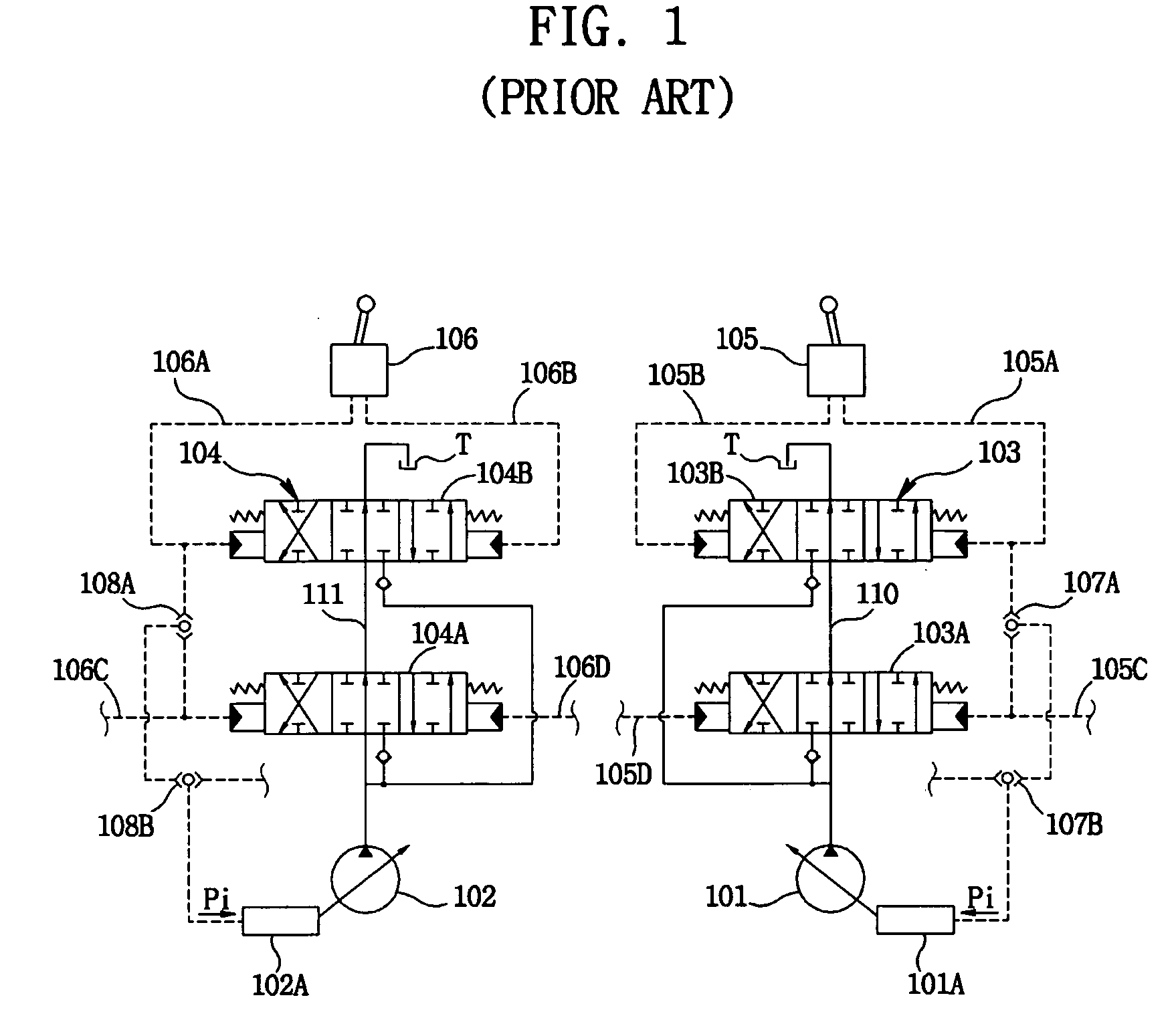
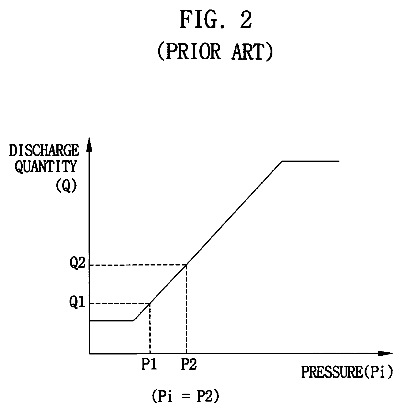
[0001] This application claims the benefit of the Korean Patent Application No. 10-2004-0116404, filed on Dec. 30, 2004, which is hereby incorporated by reference as if fully set forth herein. BACKGROUND OF THE INVENTION [0002] 1. Field of the Invention [0003] The present invention pertains to a fluid pump control system for excavators and, more specifically, to a fluid pump control system adapted for controlling a discharge quantity of a variable displacement fluid pump in proportion to a manipulation amount of a remote control valve. [0004] 2. Description of the Related Art [0005] Known systems for controlling a fluid pump in excavators include a positive pump control system that controls the discharge quantity of a pump in proportion to the magnitude of an input signal and a negative pump control system that controls the pump discharge quantity in inverse proportion to the magnitude of the input signal. [0006] One example of the positive control system is shown in FIG. 1. As show...

Claims


Application Information

Patent Timeline
IPC IPC(8): F04B49/00
CPCE02F9/2232E02F9/2285E02F9/2292E02F9/2296E02F9/20
Inventor JANG, DAL SIKJUNG, KI NAM
Owner DOOSAN INFRACORE CO LTD
Learn More