Liquid discharging partition plate for clothes dryer and clothes dryer

A technology for clothes dryers and clapboards, which is applied to household clothes dryers, applications, household appliances, etc. It can solve problems affecting drying efficiency and condensate backflow, so as to improve drying efficiency, prevent backflow into the air duct, Reduce the effect of hydraulic

Active Publication Date: 2020-07-03
WUXI FILIN ELECTRONICS CO LTD
View PDF4 Cites 10 Cited by
  • Summary
  • Abstract
  • Description
  • Claims
  • Application Information

AI Technical Summary

Problems solved by technology

[0002] When the heat pump dryer is working, due to the negative pressure in the air duct, the condensate in the liquid guide tank will flow back into the air duct, affecting the drying efficiency

Method used


Image

  • Liquid discharging partition plate for clothes dryer and clothes dryer
  • Liquid discharging partition plate for clothes dryer and clothes dryer
  • Liquid discharging partition plate for clothes dryer and clothes dryer

Examples


Embodiment Construction

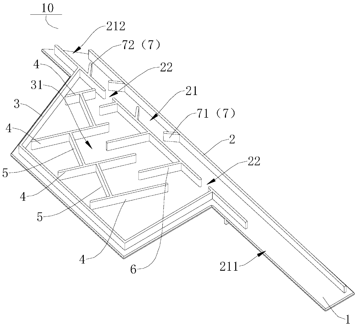
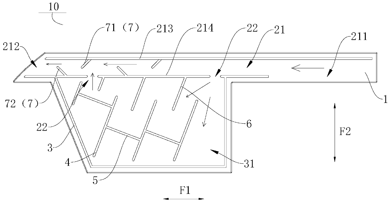
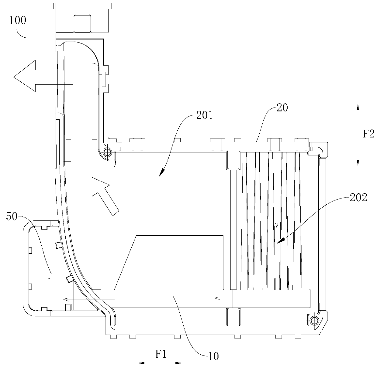
[0040] Embodiments of the present invention are described in detail below, examples of which are shown in the drawings, wherein the same or similar reference numerals designate the same or similar elements or elements having the same or similar functions throughout. The embodiments described below by referring to the figures are exemplary only for explaining the present invention and should not be construed as limiting the present invention.

[0041] In describing the present invention, it is to be understood that the terms "central", "longitudinal", "transverse", "length", "width", "thickness", "upper", "lower", "vertical", The orientation or positional relationship indicated by "horizontal", "top", "bottom", "inner", "outer", "axial", "radial", "circumferential" etc. is based on the orientation or position shown in the drawings The positional relationship is only for the convenience of describing the present invention and simplifying the description, but does not indicate or...


PUM


Abstract

The invention discloses a liquid discharging partition plate for a clothes dryer and the clothes dryer. The liquid discharging partition plate is provided with a liquid guiding groove, an inlet of theliquid guiding groove and an outlet of the liquid guiding groove are located at the two ends of the liquid guiding groove in the length direction correspondingly, the liquid discharging partition plate is further provided with a flow dividing groove, the flow dividing groove is located in at least one side of the liquid guiding groove in the width direction, and the flow dividing groove communicates with the liquid guiding groove through a liquid passing opening. According to the liquid discharging partition plate, when negative pressure is generated in an air duct, flowed-back condensate atthe outlet of the liquid guiding groove can flow to the liquid guiding groove and the flow dividing groove correspondingly so that on one hand, the flow dividing effect can be achieved, hydraulic pressure is reduced, on the other hand, condensate flowing back paths are increased, and therefore the condensate can be prevented from flowing back into the air duct.

Description

technical field [0001] The invention relates to the technical field of clothes processing equipment, in particular to a liquid drainage partition for a clothes dryer and the clothes dryer. Background technique [0002] When the heat pump dryer is working, due to the negative pressure in the air duct, the condensate in the liquid guide tank will flow back into the air duct, affecting the drying efficiency. Therefore, how to prevent the condensate from flowing back into the air duct is a technical problem urgently needed to be solved by those skilled in the art. Contents of the invention [0003] The present invention aims to solve at least one of the technical problems existing in the prior art. For this reason, an object of the present invention is to propose a kind of liquid drainage separator for clothes dryer, when negative pressure is generated in the air duct, the condensate returned at the outlet of the liquid guide groove can flow into the liquid guide groove and t...

Claims


Application Information

Patent Timeline
Patent Type & Authority Applications(China)
IPC IPC(8): D06F58/24D06F58/20
CPCD06F58/24D06F58/20
Inventor 谢邦明刘文法庾仁宗秦琼
Owner WUXI FILIN ELECTRONICS CO LTD
Why Eureka
Try Eureka