Brake apparatus, brake control unit, and brake control method
a technology of brake control unit and brake, which is applied in the direction of braking components, process and machine control, propulsion parts, etc., can solve the problem of difficulty in reducing the actual hydraulic pressure to the actual target hydraulic pressure, and achieve the effect of suppressing the occurrence of brake drag
- Summary
- Abstract
- Description
- Claims
- Application Information
AI Technical Summary
Benefits of technology
Problems solved by technology
Method used
Image
Examples
first embodiment
of the Invention
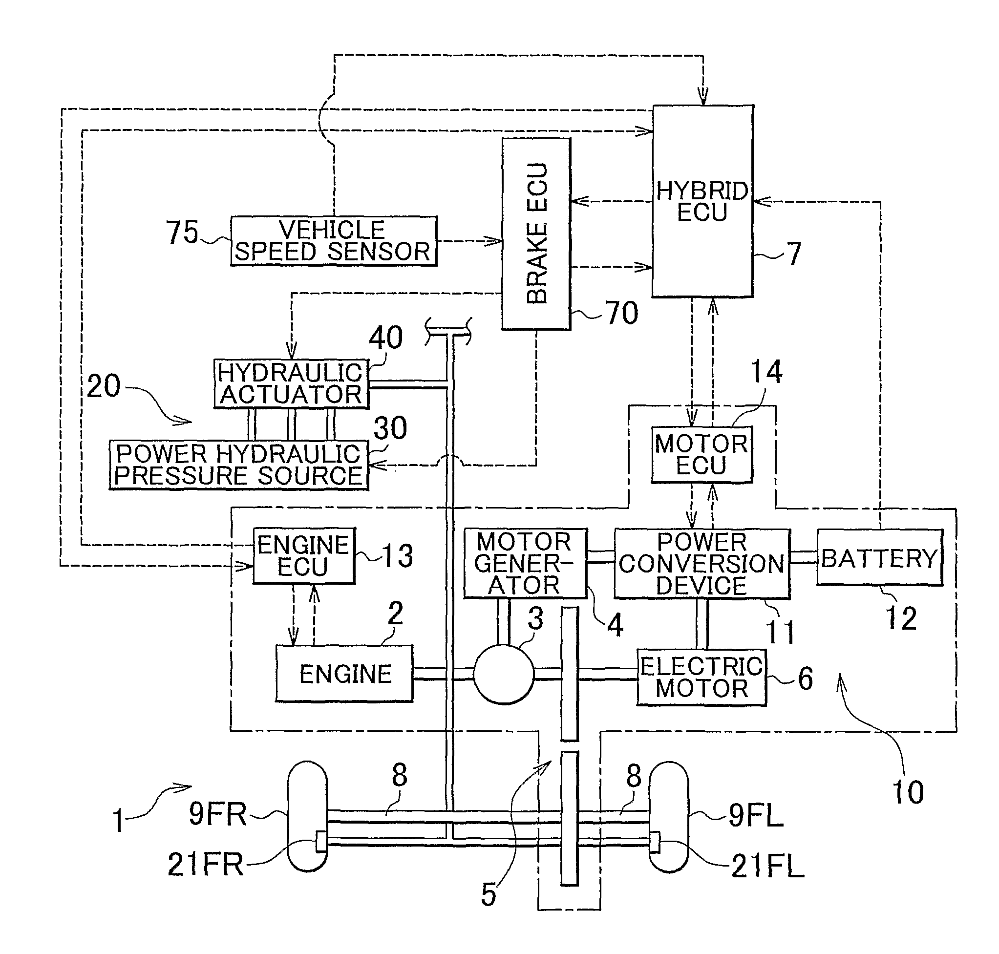
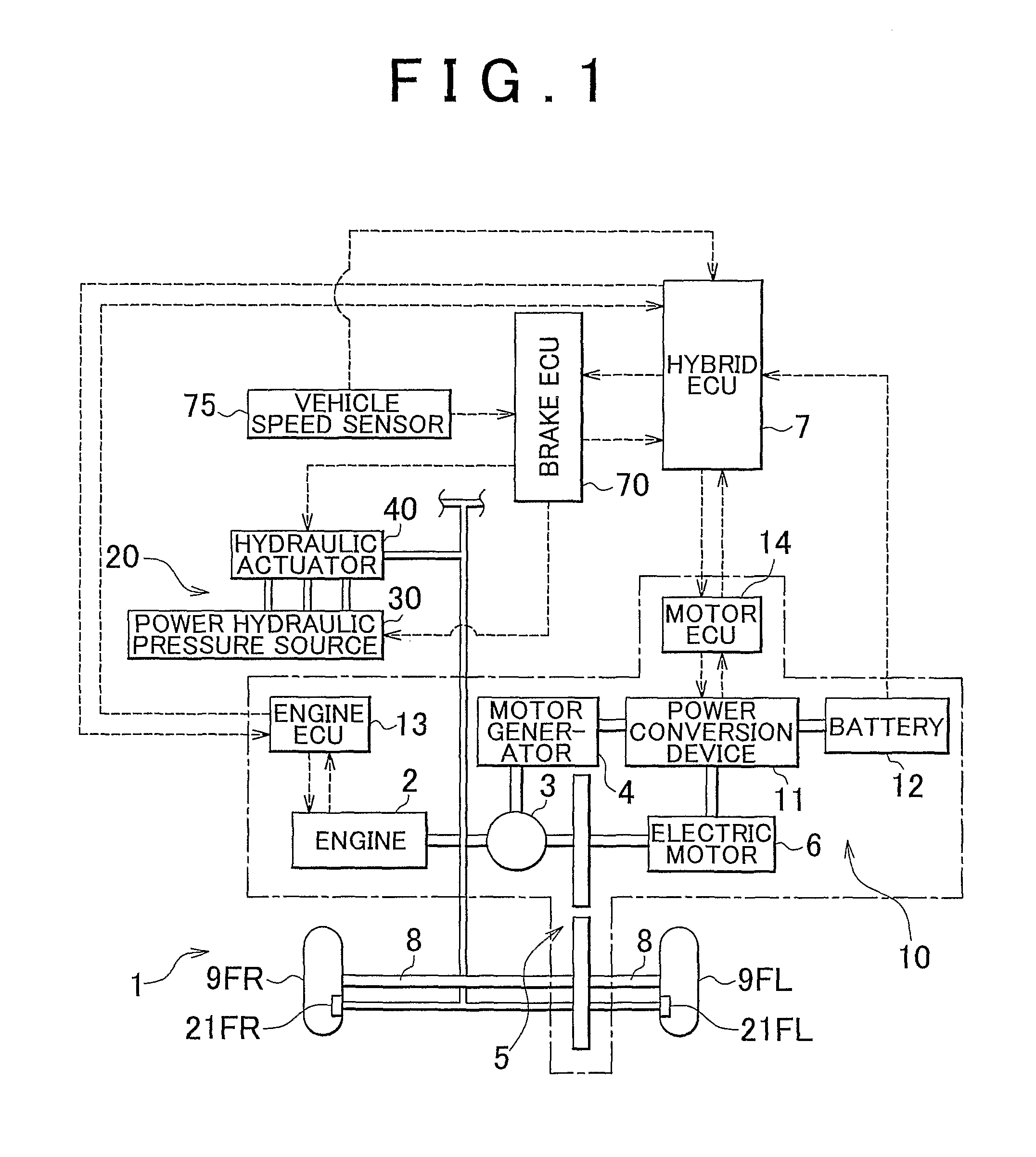
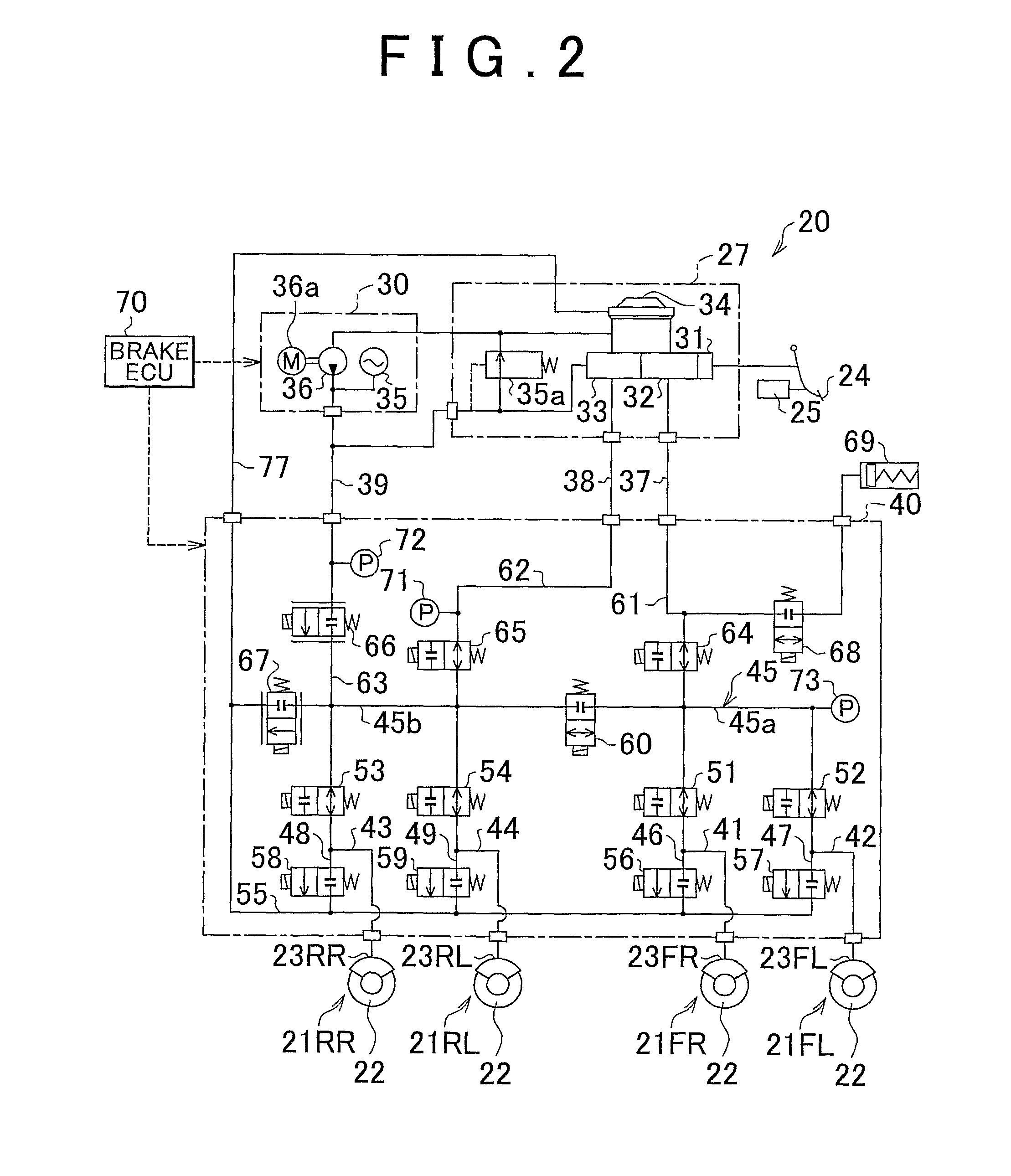
[0044]FIG. 1 is a view schematically showing a vehicle 1 provided with a brake apparatus according to a first embodiment of the invention. The vehicle 1 is a so-called hybrid vehicle. The vehicle 1 includes an engine 2, a three-axis power split mechanism 3 that is connected to a crankshaft which serves as an output shaft of the engine 2, a motor generator 4 that is connected to the power split mechanism 3 and that is able to generate electric power, an electric motor 6 that is connected to the power split mechanism 3 via a transmission 5, and electronic control units (hereinafter, referred to as “ECUs”) that control respective actuator. That is, as control units for the vehicle 1, there are provided a hybrid ECU 7 that controls the entirety of a drive system, an engine ECU 13 that controls the engine 2, a motor ECU 14 that controls each motor, and a brake ECU 70 that controls a brake. Each ECU is formed of a microprocessor that includes a CPU. Each ECU includes, in a...
second embodiment
of the Invention
[0102]Next, a second embodiment of the invention will be described. The second embodiment is mostly the same as the first embodiment except that the residual pressure reduction control is executed in controls other than the cooperative braking control. Therefore, the same reference numerals will be assigned to the components that are substantially the same as those in the first embodiment of the invention, and descriptions concerning these components will not be provided below.
[0103]FIG. 7 is a graph showing a main portion of a brake control method according to the second embodiment of the invention. FIG. 7 shows the state when the hydraulic pressure is decreased in the hydraulic braking control. FIG. 7 shows the target hydraulic pressure (indicated by a dashed line) and the actual hydraulic pressure (indicated by a solid line) of the hydraulic fluid in the hydraulic braking control. The region between the chain double-dashed lines is the dead-band region. The abscis...
PUM
 Abstract
Description
Claims
Application Information
 - R&D
- Intellectual Property
- Life Sciences
- Materials
- Tech Scout
- Unparalleled Data Quality
- Higher Quality Content
- 60% Fewer Hallucinations
Browse by: Latest US Patents, China's latest patents, Technical Efficacy Thesaurus, Application Domain, Technology Topic, Popular Technical Reports.
© 2025 PatSnap. All rights reserved.Legal|Privacy policy|Modern Slavery Act Transparency Statement|Sitemap|About US| Contact US: help@patsnap.com


