Hydraulic Cylinder of Outrigger

a hydraulic cylinder and outrigger technology, applied in the field of outriggers, can solve the problems of oil leakage from the hydraulic cylinder, heavy load applied to the rod part disposed under the cylinder part, etc., and achieve the effect of preventing damage and shortening the hydraulic hos

Inactive Publication Date: 2007-12-20
YANMAR CO LTD +1
View PDF7 Cites 9 Cited by
  • Summary
  • Abstract
  • Description
  • Claims
  • Application Information

AI Technical Summary

Benefits of technology

[0011] According to the invention, a fluid passage is formed in a rod part of the hydraulic cylinder, and a connection portion of a fluid suction and delivery port of the fluid passage to be connected to a hydraulic pressure hose is disposed adjacent to a pivot of the hydraulic cylinder. Therefore, the hydraulic pressure hose can be shortened, and the rod part of the hydraulic cylinder is prevented from being damaged. Further, the hydraulic pressure hose is prevented from being worn when it is extended or folded. Moreover, the hydraulic pressure hose is not exposed to the outside of a frame, thereby being protected from being damaged.
[0012] The hydraulic cylinder is attached to the outrigger so that, when the outrigger is extended outwardly downward, the hydraulic cylinder is disposed so as to have the rod part above its cylinder part. Therefore, the rod part of the hydraulic cylinder is prevented from being damaged.

Problems solved by technology

Still, during the rotation of the cylinder, it happens that the hydraulic pressure hose is bent and rubbed with a nearby frame or another part so as to be damaged.
Moreover, when the outrigger is lowered to support the vehicle, heavy load is applied on the rod part disposed under the cylinder part.
Further, dust such as soil easily sticks to the outer peripheral surface of the rod part at this position close to the ground, so as to damage the rod part during telescopic actuation of the hydraulic cylinder, to interfere with the telescopic actuation of the hydraulic cylinder, and to cause oil leak from the hydraulic cylinder.

Method used


Image

  • Hydraulic Cylinder of Outrigger
  • Hydraulic Cylinder of Outrigger
  • Hydraulic Cylinder of Outrigger

Examples


Embodiment Construction

[0028] An embodiment of the invention will be described.

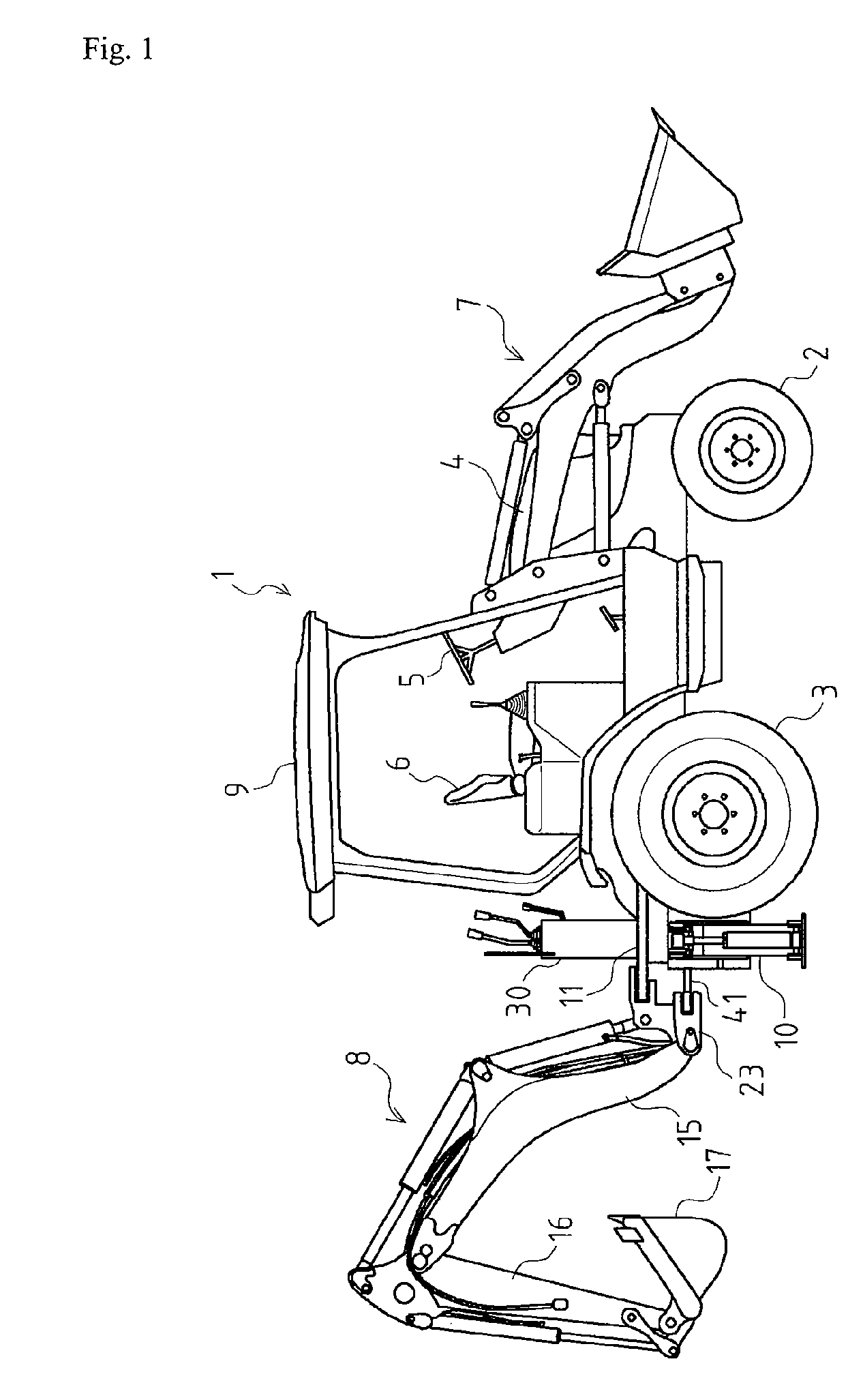
[0029] Firstly, an entire structure of a backhoe-loader 1 equipped with outriggers 10 according to the invention.

[0030] As shown in FIG. 1, backhoe-loader 1 has a body provided with a pair of front wheels 2 and a pair of rear wheels 3. On the body, a steering wheel 5 is disposed, and an operator's seat 6 is disposed behind steering wheel 5. A canopy 9 supported by four frame members is disposed above operator's seat 6. A bonnet 4 is provided on a front portion of the body so as to enclose an engine. An attitude of operator's seat 6 can be changed to face either forward or rearward. Backhoe-loader 1 is provided at a front portion of the body thereof with a front loader 7, and at a rear portion of the body thereof with a backhoe 8. An operator rotates seat 6 so as to face it forward for work by front loader 7, or to face it rearward for work by backhoe 8.

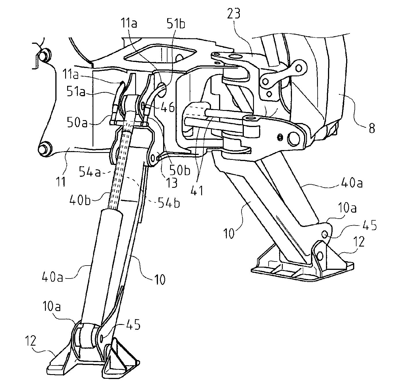
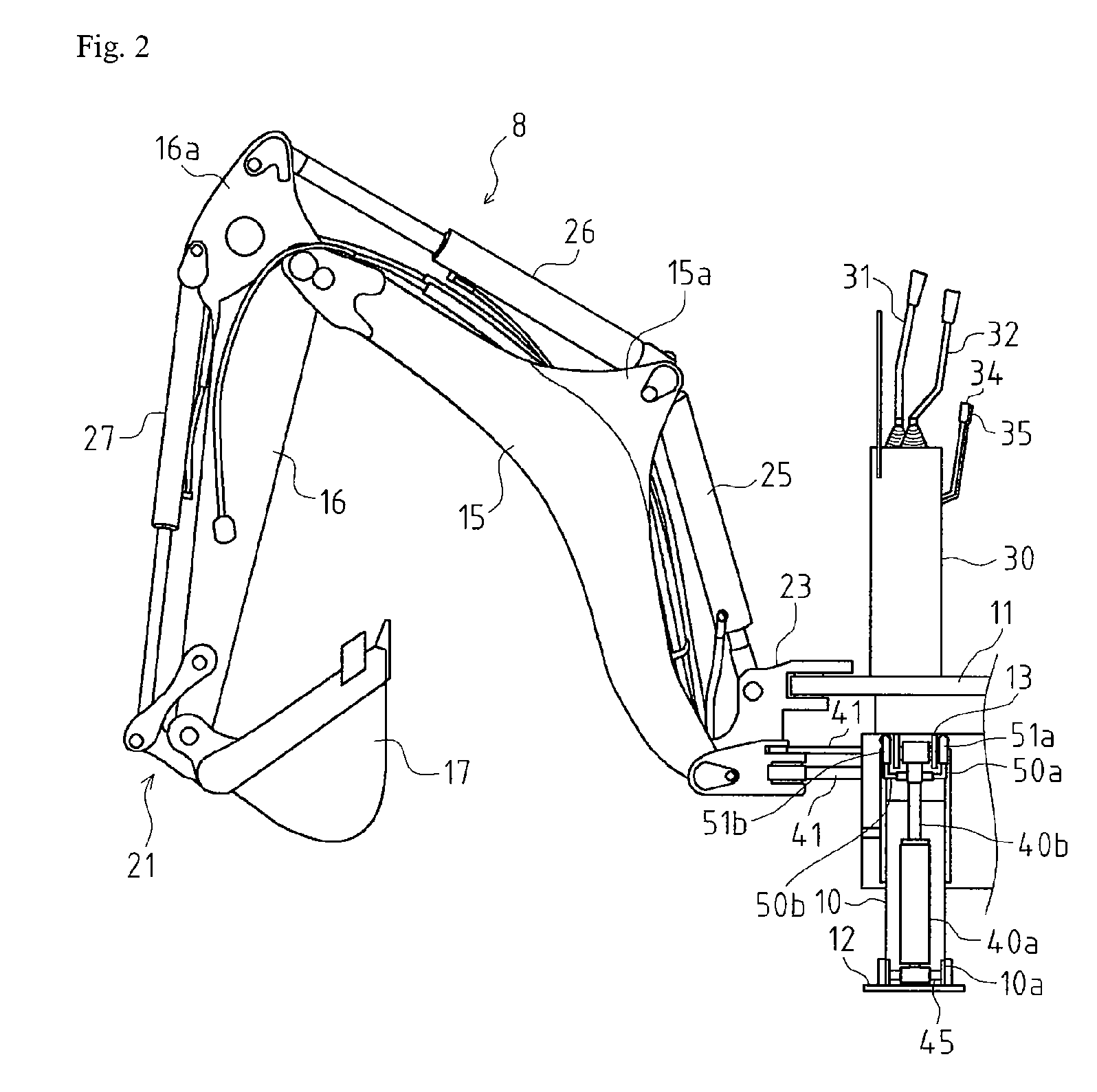
[0031] As shown in FIG. 2, backhoe 8 is attached to a machine frame 11 de...


PUM


Abstract

A structure of a hydraulic cylinder of an outrigger should be improved to prevent a hydraulic pressure hose from being damaged, and an arrangement of the hydraulic cylinder should be improved to prevent a rod part of the hydraulic cylinder from being damaged. A cylinder (40) is interposed between a machine frame and each of outriggers (10), which are vertically swingably disposed at opposite sides of the machine frame, so as to lift up and down the outrigger. Fluid passages (54a and 54b) are formed in a rod part (40b) of the hydraulic cylinder (40). Connection portions of fluid suction and delivery ports of the respective fluid passages (54a and 54b) to be connected to the respective hydraulic pressure hoses (51a and 52b) are disposed adjacent to a pivot of the hydraulic cylinder (40).

Description

TECHNICAL FIELD [0001] The present invention relates to an outrigger equipped on a construction machine, such as a backhoe, to be used for stabilizing work by the machine. Especially, it relates to a structure of a hydraulic cylinder for controlling the vertical movement of the outrigger. BACKGROUND ART [0002] Conventionally, there is a well-known technology about an outrigger equipped on a construction machine, such as a backhoe and a crane, to be used for stabilizing work at a high place. [0003] Normally, the outrigger is provided with a hydraulic cylinder whose telescopic actuation vertically swings the outrigger. The hydraulic cylinder of the outrigger is disposed so that, when the outrigger is lowered to support the vehicle, the hydraulic cylinder is disposed so as to have its cylinder part above its rod part (as disclosed in JP 5-71139A). [0004] The conventional hydraulic cylinder of the outrigger is vertically rotated together with the vertically rotated outrigger, thereby be...

Claims


Application Information

Patent Timeline
Patent Type & Authority Applications(United States)
IPC IPC(8): F16J10/00
CPCE02F9/085F15B15/149E02F9/2275
Inventor SAKADA, SEIJIOOTSUKI, HIROYUKI
Owner YANMAR CO LTD
Why Eureka
Try Eureka