
System and method for tool testing and alignment

a multi-axis machine and tool tip technology, applied in the direction of process and machine control, program control, instruments, etc., can solve the problems of extended machine downtime, process is also prone to errors,

Active Publication Date: 2012-03-15
FLOW INT
View PDF3 Cites 31 Cited by
  • Summary
  • Abstract
  • Description
  • Claims
  • Application Information

AI Technical Summary

Benefits of technology

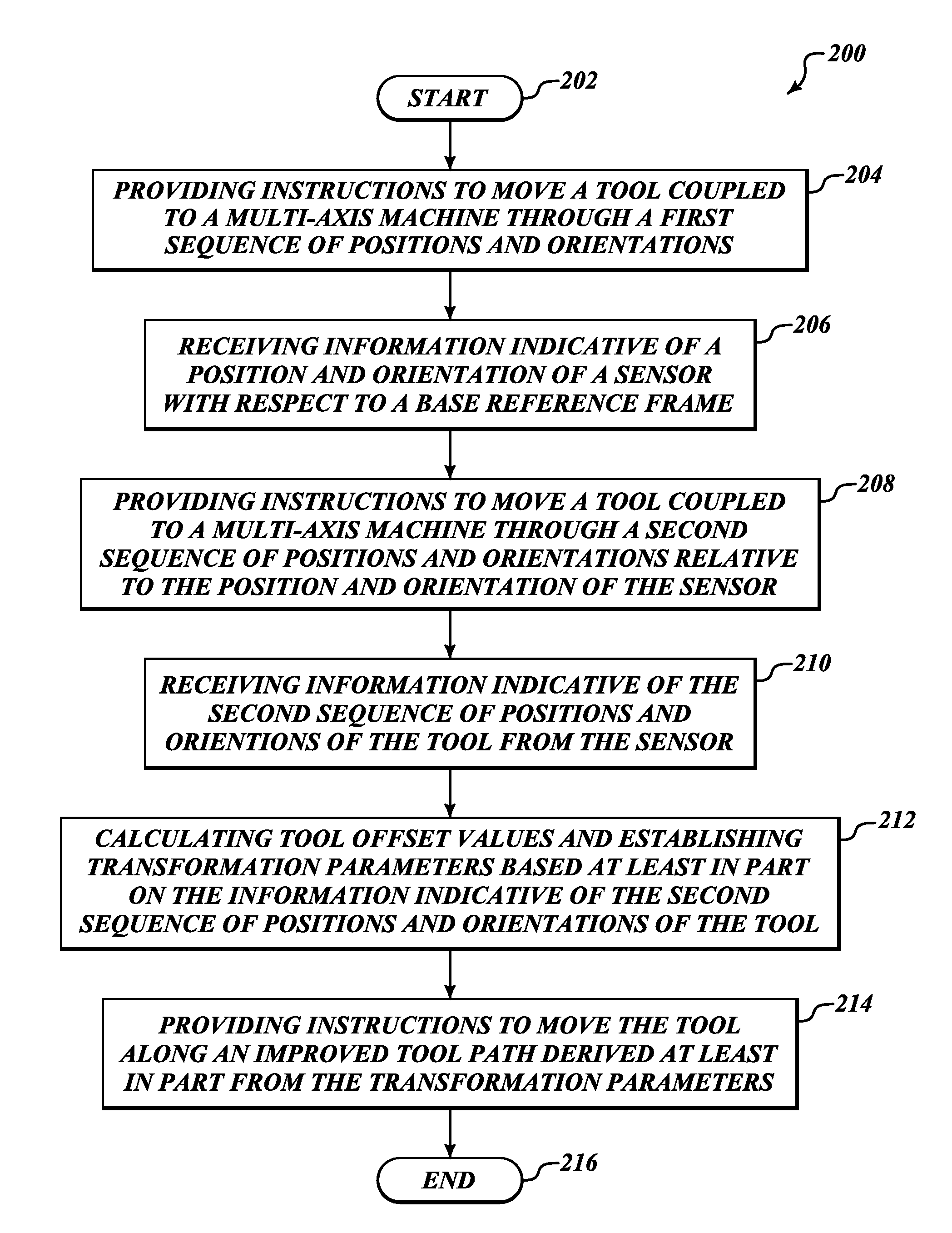
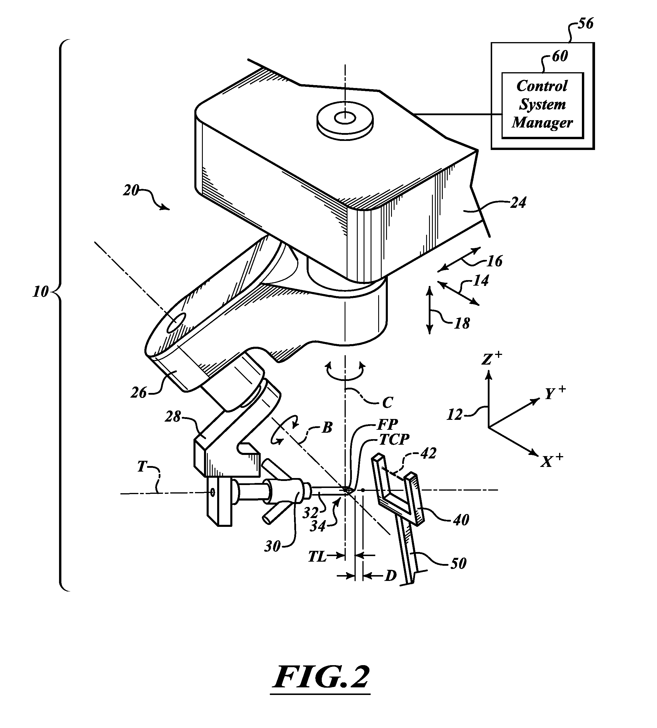
[0010]Embodiments described herein provide enhanced systems and methods for improving a tool tip path (i.e. the path along and orientation in which a tip of the tool moves and is directed during operation) of a waterjet cutting machine or the like by testing and compensating for tool misalignment.

Problems solved by technology

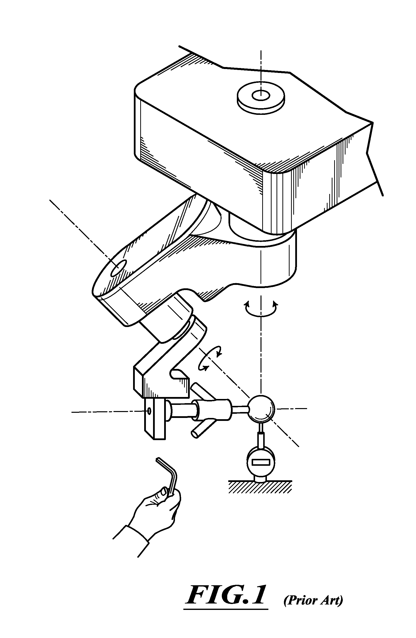
This process requires iterative measurements and adjustments as the physical adjustment of the probe with respect to one axis of rotation or translation can cause misalignment with respect to the other axes of rotation or translation.
The process is also prone to errors and can be extremely laborious and time-consuming resulting in extended periods of machine downtime.
Still further, because the process requires the replacement of a probe with a cutting head or other tool it is prone to the introduction of misalignment at the time the probe is exchanged with the cutting head or other tool prior to processing a workpiece.

Method used


Image

  • System and method for tool testing and alignment
  • System and method for tool testing and alignment
  • System and method for tool testing and alignment

Examples


Embodiment Construction

[0029]In the following description, certain specific details are set forth in order to provide a thorough understanding of various disclosed embodiments. However, one skilled in the relevant art will recognize that embodiments may be practiced without one or more of these specific details. In other instances, well-known structures and control techniques associated with waterjet cutting machines or other multi-axis machines may not be shown or described in detail to avoid unnecessarily obscuring descriptions of the embodiments.

[0030]Unless the context requires otherwise, throughout the specification and claims which follow, the word “comprise” and variations thereof, such as, “comprises” and “comprising” are to be construed in an open, inclusive sense, that is as “including, but not limited to.”

[0031]Reference throughout this specification to “one embodiment” or “an embodiment” means that a particular feature, structure or characteristic described in connection with the embodiment is...


PUM


Abstract

A system and method for improving a tool tip path of a machine, such as a waterjet cutting machine, by testing and compensating for tool misalignment. The system and method using a sensor positioned to sense a portion of the machine, such as a cutting head assembly, during a sequence of movements thereof and configured to output information indicative of various positions and orientations of a tool of the machine so as to generate an improved tool tip path based on transformation parameters derived from such information.

Description

BACKGROUND[0001]1. Technical Field[0002]This disclosure relates to a system and method for improving a tool tip path of a multi-axis machine by testing and compensating for tool misalignment, and in some embodiments, is directed to a system and method for improving a tool tip path of a waterjet cutting machine by testing and compensating for tool misalignment.[0003]2. Description of the Related Art[0004]High-pressure fluid jets, including high-pressure abrasive waterjets, are used to cut a wide variety of materials in many different industries. Abrasive waterjets have proven to be especially useful in cutting difficult, thick, or aggregate materials, such as thick metal, glass, or ceramic materials. Systems for generating high-pressure abrasive waterjets are currently available, such as, for example, the Mach 4™ 5-axis abrasive waterjet system manufactured by Flow International Corporation, the assignee of the present invention, as well as other systems that include an abrasive wate...

Claims


Application Information

Patent Timeline
IPC IPC(8): G06F19/00
CPCB24C1/045B24C9/00G05B2219/50139G05B2219/45036G05B2219/50028G05B19/401Y10T83/364Y10T83/0591
Inventor KNAUPP, MICHAELMEYER, ANDREAS
Owner FLOW INT
Learn More