
Systems and methods of providing a tcas primary radar

a primary radar and radar system technology, applied in the field of radar systems, can solve the problems of uas aircraft being significantly heavier, having transponders, and not being able to respond to tcas interrogations

Active Publication Date: 2012-03-22
AVIATION COMM AMP SURVEILLANCE SYST LLC
View PDF4 Cites 16 Cited by
  • Summary
  • Abstract
  • Description
  • Claims
  • Application Information

AI Technical Summary

Benefits of technology

[0014]In accordance with an embodiment of the present invention, a system is disclosed for use on a UAS. The system comprises a TCAS having at least a transceiver and an antenna, and a processor coupled to the transceiver for receivi

Problems solved by technology

However, there are other objects or vehicles, as described above, that do not possess transponders, i.e., are non-equipped, and cannot therefore provide replies to TCAS interrogations.
Existing methods, such as those set forth above, are disadvantageous in that they require use of a separate primary radar tracking device and an antenna, each of which add considerable weight to a UAS aircraft.
Adding such weight to a UAS aircraft limits the payload weight that a UAS aircraft can carry, which may exclude the ability to carry on the UAS aircraft other devices and systems, such as a TCAS which may be needed to fly within the NAS without having to obtain special approval on a case-by-case basis.
Such new modulation would likely have to be approved for use by the FAA, the Federal Communications Commission (FCC) and other international bodies before the technique could be used, such approval processes typically being lengthy in duration.
Moreover, all equipment fielded to date is not capable of providing the necessary new modulation waveforms to utilize the methods of U.S. Pat. No. 7,414,567.
Another difficulty with U.S. Pat. No. 7,414,567 is that the waveform being used for the radar function is 120 microseconds long.
Since a range of interest for UAS aircraft to detect non-equipped airborne objects and vehicles may be from 0 to 5 (or 0 to 10) nautical miles from the UAS aircraft, the radar function disclosed by U.S. Pat. No. 7,414,567, having the noted blind spot of 0 to 10 nautical miles, is not viable for use on UAS aircraft.

Method used


Image

  • Systems and methods of providing a tcas primary radar
  • Systems and methods of providing a tcas primary radar
  • Systems and methods of providing a tcas primary radar

Examples


Embodiment Construction

[0024]Reference will now be made in detail to the present exemplary embodiments of the invention, examples of which are illustrated in the accompanying drawings.

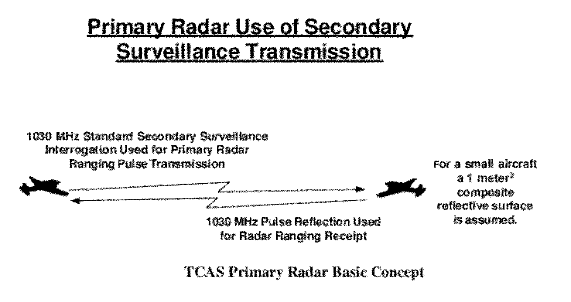
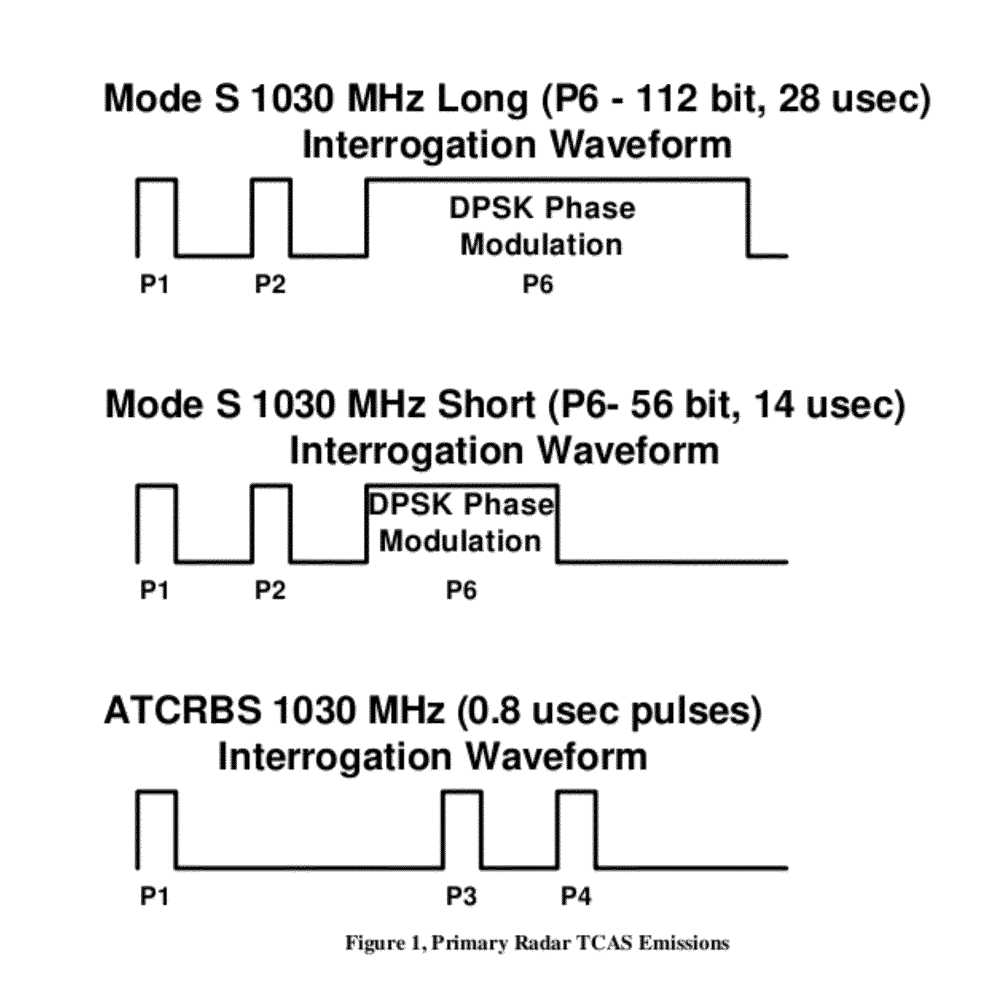
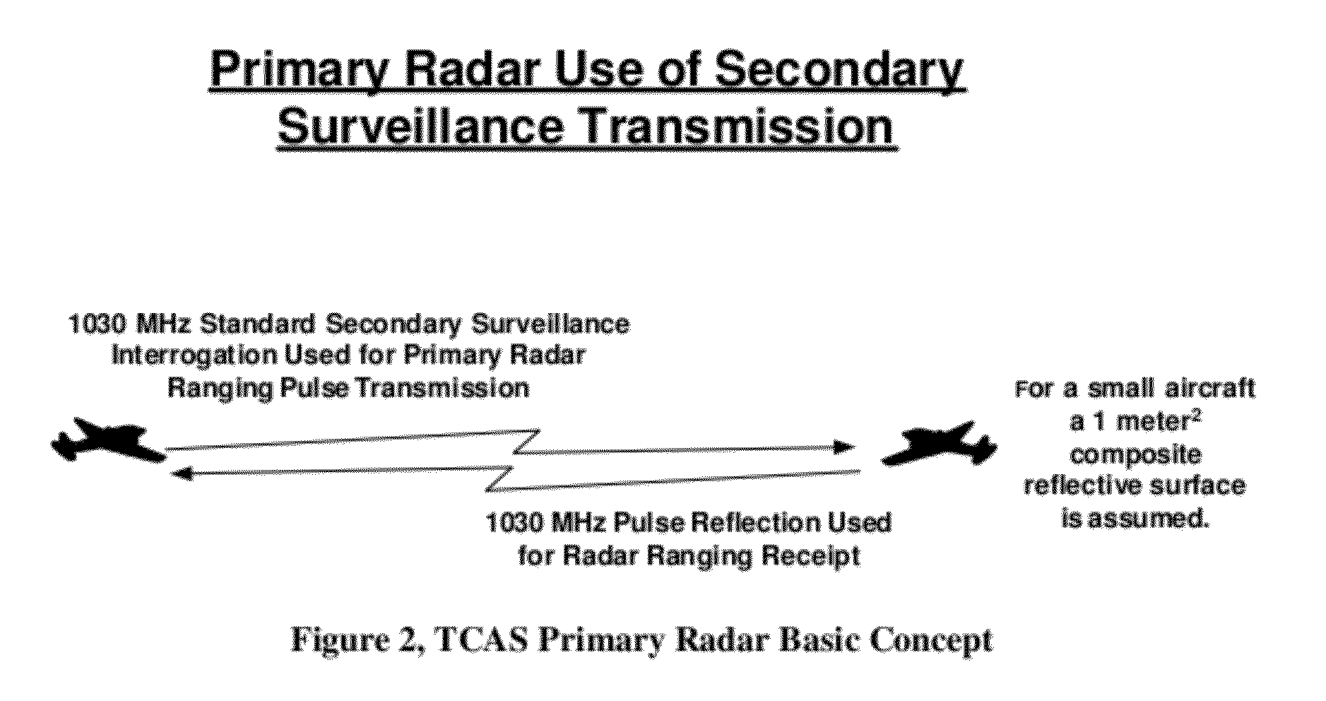
[0025]Embodiments of the present invention primarily disclose systems and methods for using a TCAS RF platform to provide a primary radar function using the already existing industry standard waveforms and modulation required for TCAS secondary surveillance. Such embodiments allow for existing industry standard waveforms and modulations of TCAS, as described in RTCA DO-185B, to be used to provide a primary tracking radar function without the need for any new non-TCAS-industry standard modulation.

[0026]Embodiments of the present invention may use the Mode S and ATCRBS interrogation waveforms already being generated and transmitted on 1030 MHz by TCAS for secondary surveillance radar as the emissions to be used for the primary surveillance radar function. Exemplary Mode S interrogation emissions are shown in FIG. 1 and already...


PUM


Abstract

Systems and related methods are delineated for employing a TCAS to provide a radar function for a UAS. One such system comprises a TCAS having at least a transceiver and an antenna, and a processor coupled to the transceiver for receiving signals generated from receipt of reflected energy received over the antenna, the reflected energy resulting from the one or more of a Mode S interrogation waveform and an ATCRBS interrogation waveform transmitted from the antenna.

Description

CROSS REFERENCE TO RELATED APPLICATIONS[0001]This application is related to and claims priority from U.S. provisional patent application 61 / 285,489, entitled TCAS PRIMARY RADAR SYSTEMS AND METHODS and filed on Dec. 10, 2009 in the name of Gregory T. Stayton. This related application is hereby incorporated by reference in its entirety for all purposes.BACKGROUND OF THE INVENTION[0002]1. Field of the Invention[0003]The present invention relates to radar systems, and more particularly, systems and methods of employing a traffic collision avoidance system (TCAS) to provide a radar function for an unmanned aircraft system (UAS).[0004]2. Description of the Related Art[0005]An unmanned aerial vehicle (UAV) (known also as a remotely piloted vehicle (RPV) or an unmanned aircraft system (UAS)) is an aircraft that is flown by a pilot or a navigator (sometimes referred to as a Combat Systems Officer) without a human crew member on board the aircraft. There is a wide variety of UAV shapes, sizes...

Claims


Application Information

Patent Timeline
IPC IPC(8): G01S13/93G01S13/933
CPCG01S13/9303G01S3/023G01S13/933
Inventor STAYTON, GREGORY T.
Owner AVIATION COMM AMP SURVEILLANCE SYST LLC
Learn More