Antenna with tapered array

Active Publication Date: 2012-03-22
TOYOTA JIDOSHA KK +1
View PDF5 Cites 0 Cited by
  • Summary
  • Abstract
  • Description
  • Claims
  • Application Information

AI Technical Summary

Problems solved by technology

This concentration affects the radiation efficiency of the antenna, and may gener

Method used


Image

  • Antenna with tapered array
  • Antenna with tapered array
  • Antenna with tapered array

Examples


Example

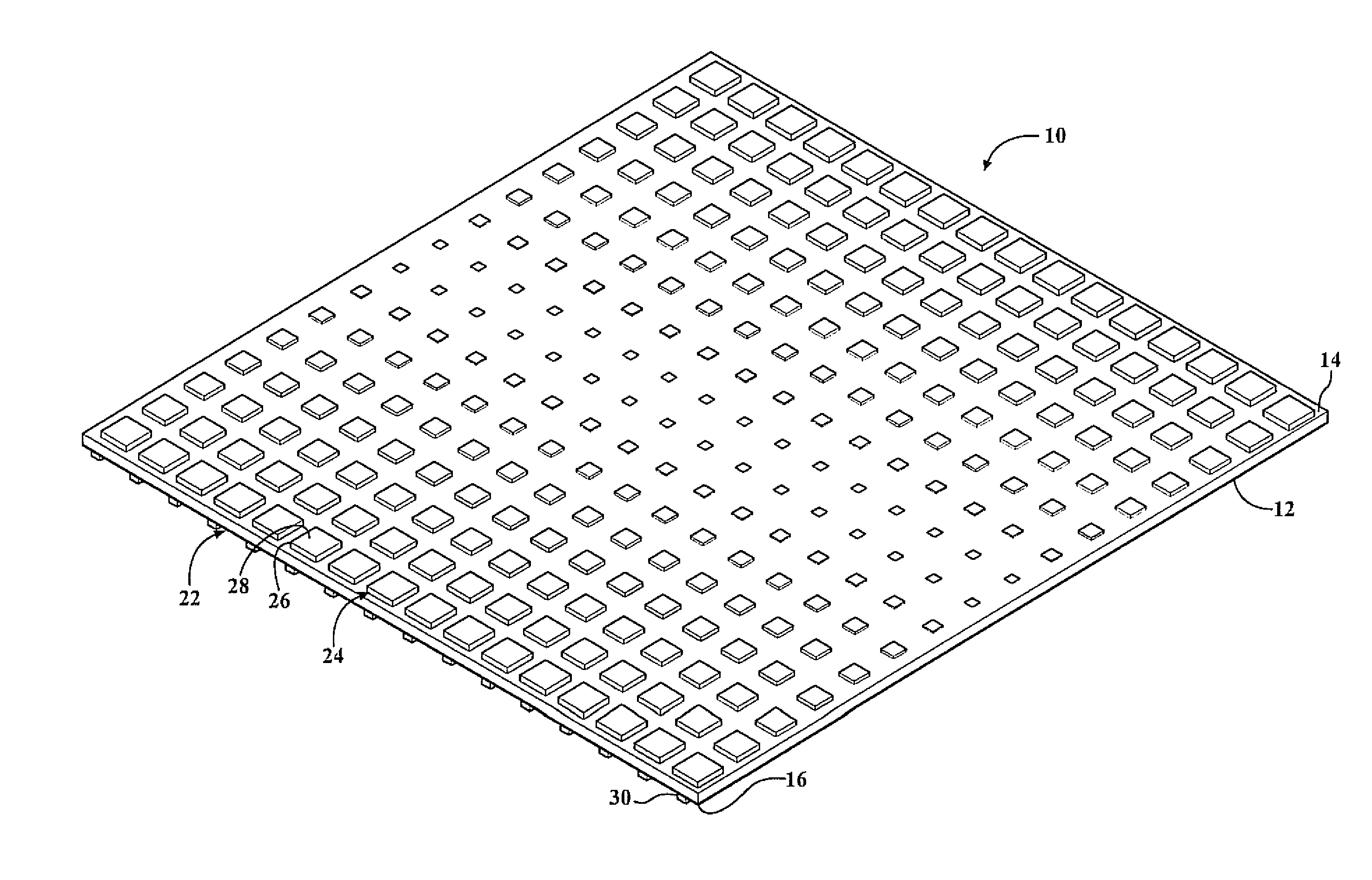
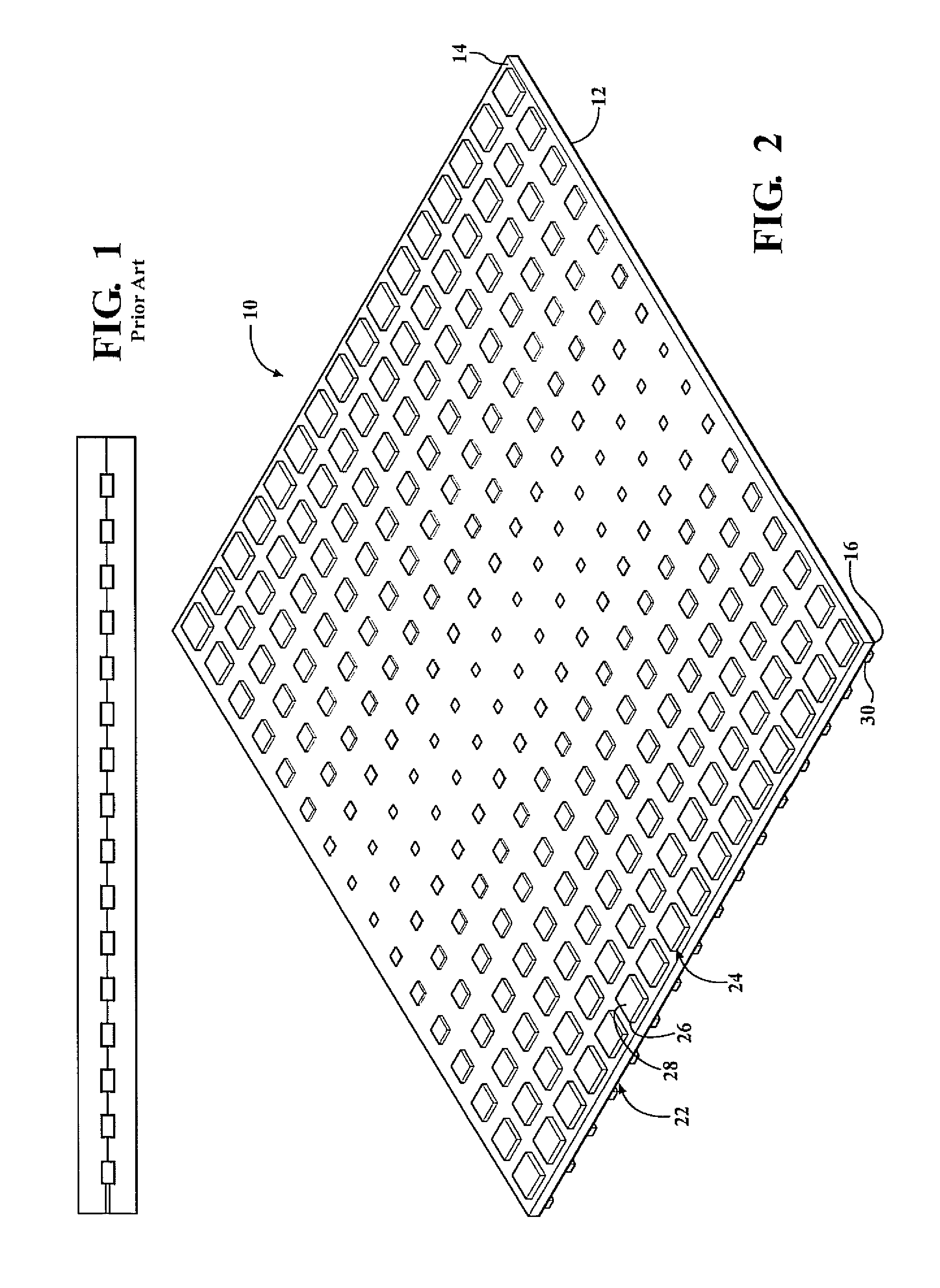
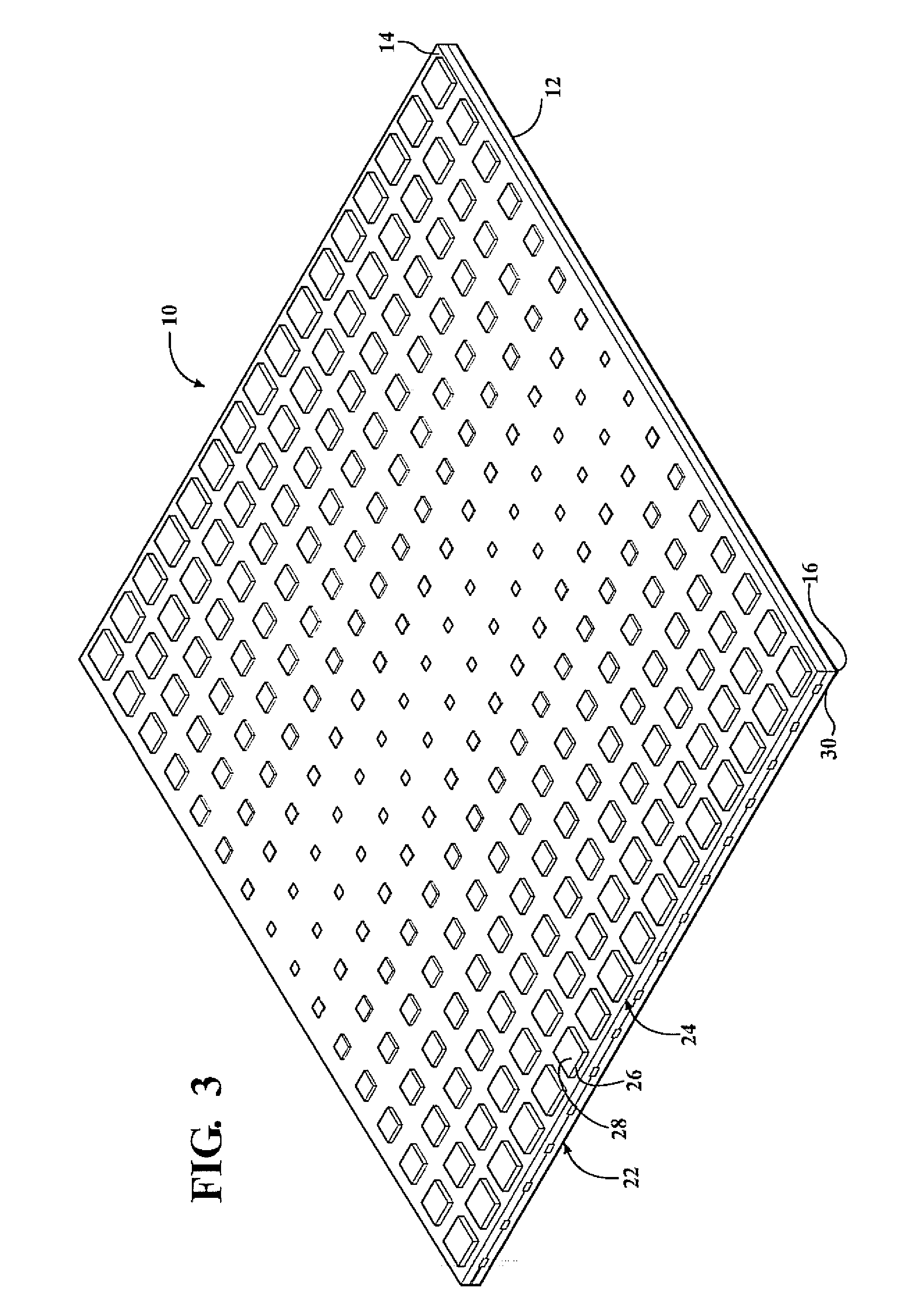
[0012]With reference first to FIG. 2, an antenna 10 having a uniform distribution of an electrical field is shown. The uniform distribution of electrical field improves the radiation efficiency of the antenna 10 and reduces the size of side lobes.

[0013]The antenna 10 includes a substrate 12 formed of a dielectric material. The substrate 12 includes a first surface 14 opposite a second surface 16. The substrate 12 may be formed of multiple layers 18, 20 of dielectric material. The substrate 12 has a predetermined thickness configured to optimize the radiation efficiency of the antenna 10.

[0014]An antenna array 22 is disposed on the first surface 14 of the substrate 12. The antenna array 22 has a plurality of resonating lines 24, and each resonating line 24 has a plurality of resonators 26 axially aligned to each other. Each of the plurality of resonators 26 has a resonating surface 28. The resonating surfaces 28 of the resonators 26 at the ends of the resonating line 24 are larger th...


PUM


Abstract

An antenna with improved radiation efficiency is provided. The antenna includes an antenna array proximately coupled to a feed line. The antenna array includes a plurality of resonating lines. Each resonating line includes a plurality of axially aligned resonators. The resonators have a resonating surface. The resonating surfaces of the resonators at the ends of the resonating lines are larger than resonating surfaces of the resonators in the middle of the resonating lines. Power is supplied to each resonating ling through a feed line. Electrical field is uniformly distributed along the antenna array so as to improve the radiation efficiency of the antenna.

Description

FIELD OF THE INVENTION[0001]The invention relates to an antenna configured to improve radiation efficiency.BACKGROUND OF THE INVENTION[0002]Current radar systems operating at the microwave range include an antenna. The antenna includes an array of resonating elements mounted onto a substrate. The antenna array includes a plurality of resonating lines. Each resonating line includes a plurality of axially aligned resonators. Power is supplied to each resonating line through a feed line.[0003]In certain embodiments, the feed line is proximately coupled to each of the resonating lines. The feed lines are mounted on the substrate and are generally disposed beneath the resonating lines. Electricity is supplied along the feed lines, actuating the resonators so as to receive echoes from a transmitting antenna. However, a concentration of electrical field forms along the mid portion of the antenna array, as shown in FIG. 1. This concentration affects the radiation efficiency of the antenna, ...

Claims


Application Information

Patent Timeline
IPC IPC(8): H01Q21/00
CPCH01Q13/206H01Q21/30H01Q21/22H01Q21/061
Inventor LEE, JAE SEUNGSCHMALENBERG, PAUL D.RIDA, AMINLI, RONGLINTENTZERIS, EMMANOUIL M.
Owner TOYOTA JIDOSHA KK
Why Eureka
Try Eureka