
Image forming apparatus, image forming method, and computer program product

Inactive Publication Date: 2012-03-22
RICOH KK
View PDF3 Cites 5 Cited by
  • Summary
  • Abstract
  • Description
  • Claims
  • Application Information

AI Technical Summary

Benefits of technology

[0013]According to still another aspect of the present invention, there is provided a computer program product comprising a non-transitory computer readable medium including programmed instructions. The instructions, when executed by a computer, cause the computer to perform: storing print data and first converted data in a storage unit, the first converted data being obtained by reflecting a first print condition in the print data and converting the print data into a printable form; receiving an input of a reprint instruction to reprint the first converted data; acquiring a second print condition for reprinting the first converted data; determining, when the input of the reprint instruction is received, whether the first converted data is printable in the second print condition by comparing the acquired second print condition against the first print condition reflected in the first converted data; acquiring, when it is determined that the first converted data is unprintable in the second print condition acquired at the acquiring, the print data from the storage unit, and converting the print data into second converted data by reflecting the second print condition in the print data; and printing the second converted data.

Problems solved by technology

However, it is not possible by using the method disclosed in Japanese Patent Application Laid-open No. 2009-037409 to reflect, when reprinting a stored document, a change made to print-related condition of the document after the document has been stored, in the print-related condition.
It is not possible by using the method disclosed in Japanese Patent Application Laid-open No. 2004-288032 to reflect, when reprinting a print hold job, a change made to print-related condition of the print hold job into the print-related condition.
The methods of Japanese Patent Application Laid-open No. 2009-037409 and Japanese Patent Application Laid-open No. 2004-288032 exhibit poor operability because, each time when reprinting is to be performed, the methods force a user to determine applicable conditions and set the conditions individually in order to reflect, in the condition, the change made after the document has been stored or after the print job has been stored.
A configuration in which print condition is automatically and invariably set to the same print condition as those at a time of storage of the document or the print job can disadvantageously lead to degradation in image quality because the condition cannot be set to be suitable for equipment, by which the print data is to be output.

Method used


Image

  • Image forming apparatus, image forming method, and computer program product
  • Image forming apparatus, image forming method, and computer program product
  • Image forming apparatus, image forming method, and computer program product

Examples


Embodiment Construction

[0029]Exemplary embodiments of the present invention will be described in detail below with reference to the accompanying drawings.

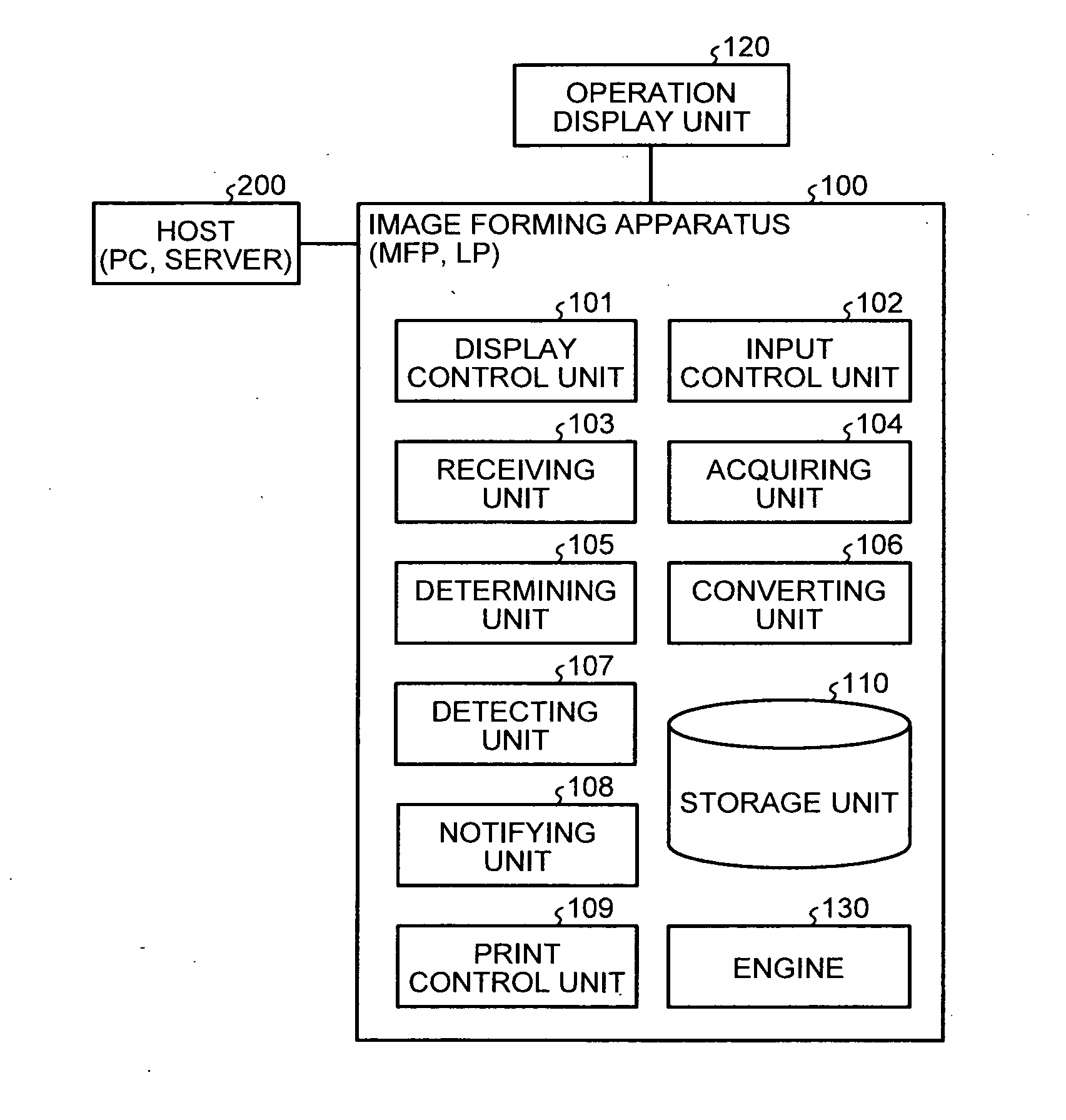
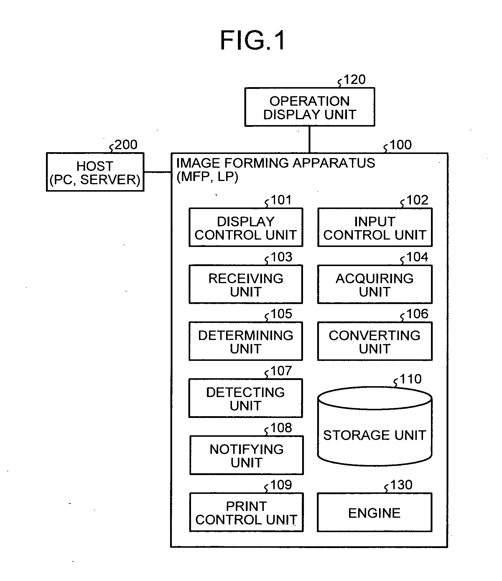
[0030]FIG. 1 is a block diagram illustrating the configuration of an image forming system according to an embodiment of the present invention. As illustrated in FIG. 1, the image forming system includes a host 200, which is a personal computer (PC) or a server, and an image forming apparatus 100, which is a multifunction printer (MFP) or a laser printer (LP), that is connected to the host 200.

[0031]As illustrated in FIG. 1, the image forming apparatus 100 includes a display control unit 101, an input control unit 102, a receiving unit 103, an acquiring unit 104, a determining unit 105, a converting unit 106, a detecting unit 107, a notifying unit 108, a print control unit 109, an operation display unit 120, a storage unit 110, and an engine 130.

[0032]The receiving unit 103 receives print data from the host 200 and stores the received print data in the st...


PUM


Abstract

An image forming apparatus includes a storage unit that stores therein print data and first converted data obtained by reflecting a first print condition in the print data and converting the print data into a printable form; an input receiving unit that receives an input of a reprint instruction to reprint the first converted data; an acquiring unit that acquires a second print condition for reprinting the first converted data; a determining unit that determines whether the first converted data is printable in the second print condition by comparing the acquired second print condition against the first print condition; a converting unit that converts, when it is determined that the first converted data is unprintable in the second print condition, the print data into second converted data by reflecting the second print condition in the print data; a print control unit prints out the second converted data.

Description

CROSS-REFERENCE TO RELATED APPLICATIONS[0001]The present application claims priority to and incorporates by reference the entire contents of Japanese Patent Application No. 2010-208475 filed in Japan on Sep. 16, 2010.BACKGROUND OF THE INVENTION[0002]1. Field of the Invention[0003]The present invention relates to an image forming apparatus, an image forming method, and a computer program product.[0004]2. Description of the Related Art[0005]Techniques of converting print data described in page description language (PDL) or the like into converted data, which reflects print condition, in a printable form with a raster image processor (RIP) have been known in recent years. Meanwhile, methods of speeding up a printing process during reprinting by using converted data converted by an RIP are conventionally developed.[0006]For example, a method of managing print data entities associated with contents of past print requests so that, in the case that a user performs reprinting of print data ...

Claims


Application Information

Patent Timeline
IPC IPC(8): G06K15/02
CPCG06K15/02G06K15/186G06K15/1825G06K15/4095G06K15/1814G06K15/408
Inventor SAITO, YUKAOKADA, DAISUKESHINDO, NOBUHIROMATSUI, HIDEAKIKUBO, NAOHIKOIWATA, NOBUYUKIHAYASHI, MASAHIRO
Owner RICOH KK
Learn More