Computed tomography detector module

Active Publication Date: 2012-03-22
ANALOG DEVICES INC
View PDF7 Cites 23 Cited by
  • Summary
  • Abstract
  • Description
  • Claims
  • Application Information

AI Technical Summary

Problems solved by technology

Several problems exist, however, in designing and constructing CT scanners.
However, achieving desirable performance metrics of the detector module 28 in the operational environment of the CT scanner 20 can conflict with this desire to reduce the module

Method used


Image

  • Computed tomography detector module
  • Computed tomography detector module
  • Computed tomography detector module

Examples


Embodiment Construction

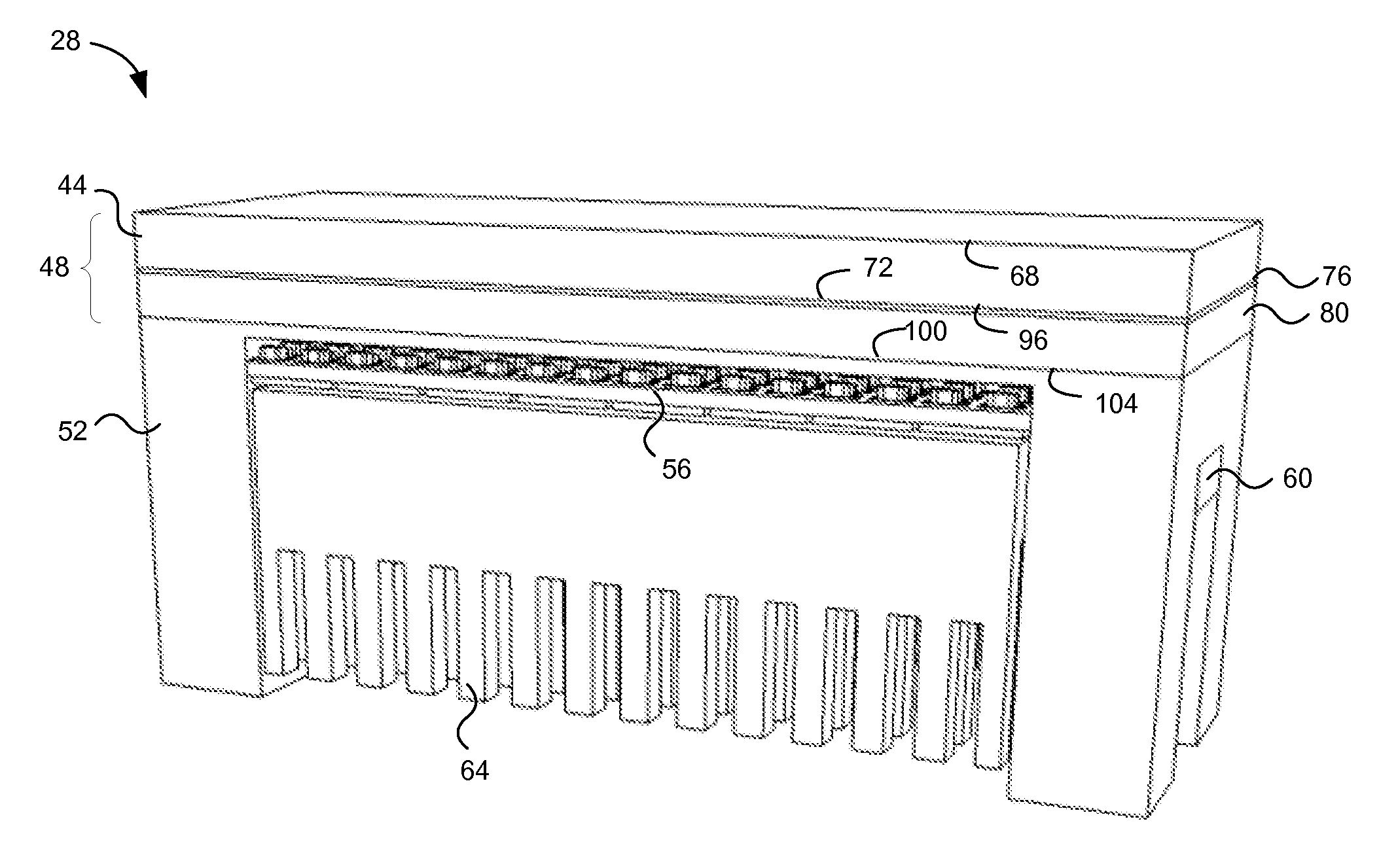
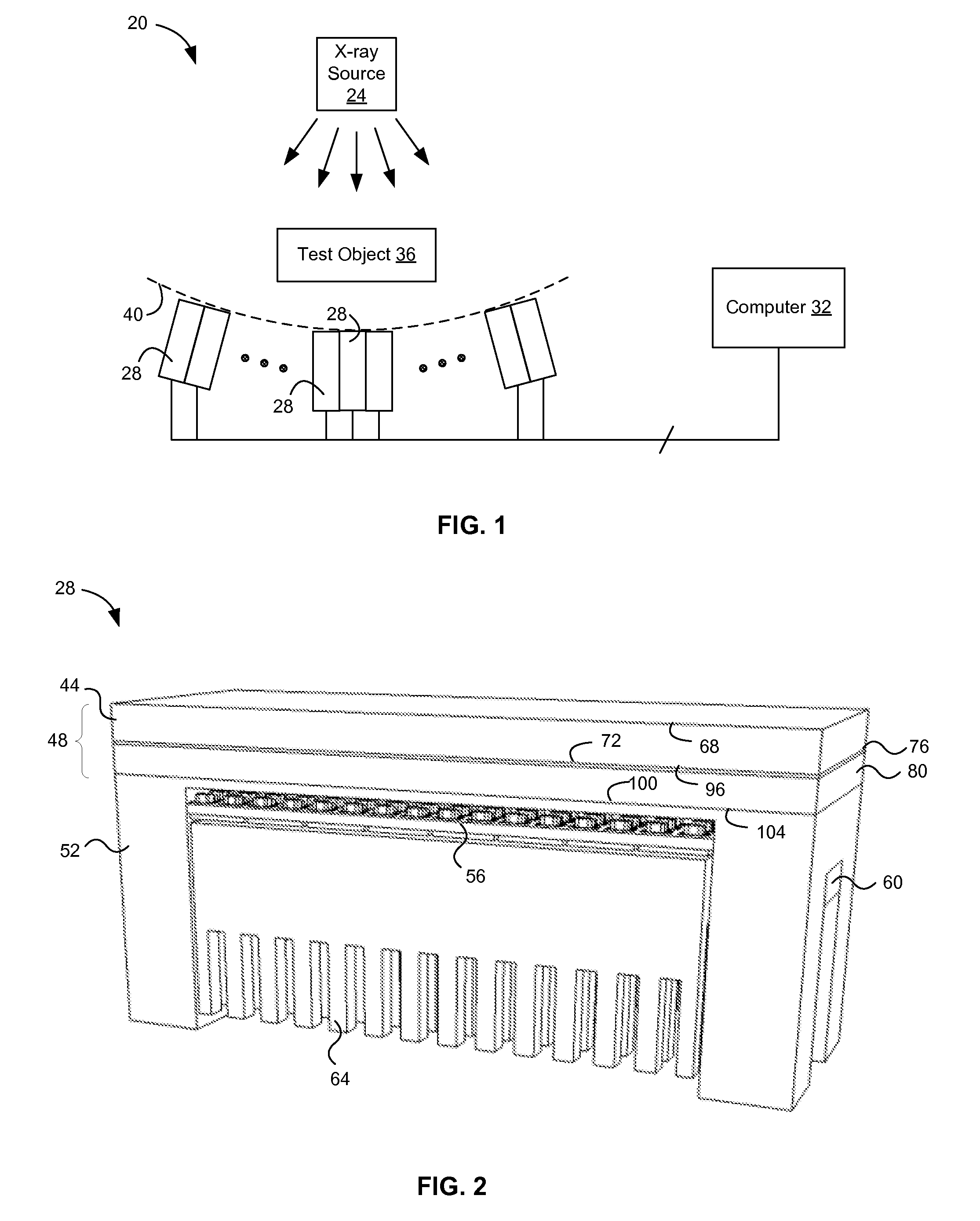
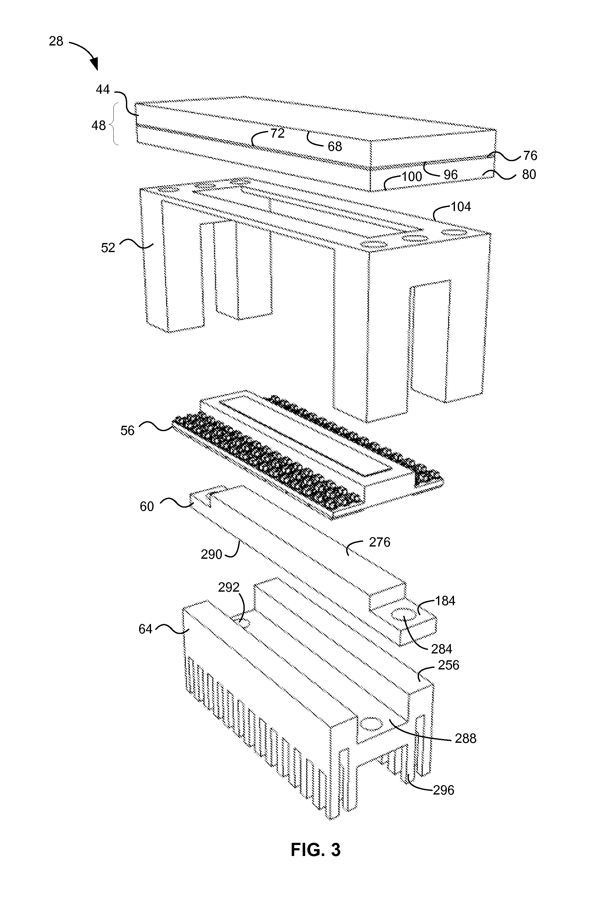
[0020]An embodiment of the computed tomography detector module 28 can include a detector element, a frame, and a converter element. The detector element can be configured to detect electromagnetic radiation at a detection plane and output one or more analog detection signals. The frame can be configured to connect to the detector element and include a shield portion, parallel to the detection plane, to at least partially block X-rays. The converter element can include a substrate having a connector portion and a component portion, the connector portion thicker in a direction perpendicular to the detection plane than the component portion and configured to extend through an aperture of the frame, and the component portion having at least one substrate surface parallel to the detection plane with one or more electrical components attached thereto. The detector module can also include a heat sink separated from the component substrate portion and components attached thereto by a separa...


PUM


Abstract

A computed tomography detector module can include a detector element, a frame, and a converter element. The detector element can be configured to detect electromagnetic radiation at a detection plane and output one or more analog detection signals. The frame can connect to the detector element and include a shield portion, parallel to the detection plane, configured to at least partially block X-rays. The converter element can include a substrate having connector and component substrate portions, the connector substrate portion thicker in a direction perpendicular to the detection plane than the component substrate portion and configured to extend through an aperture of the frame, the component substrate portion having at least one substrate surface parallel to the detection plane with one or more electrical components attached thereto. The detector module can optionally include a heat sink, which can have a top surface separated from the component substrate portion and components attached thereto by a separation gap. A computed tomography scanner can include the detector module.

Description

BACKGROUND INFORMATION[0001]Computed tomography (CT) scanners can be used to produce two- and three-dimensional digital images of test objects. FIG. 1 depicts an exemplary embodiment of a CT scanner 20 having an X-ray source 24, a plurality of detector modules 28, and a computer 32. The X-ray source 24 produces X-rays in a direction toward a test object 36 and the detector modules 28. The detector modules 28 can convert X-rays arriving at the modules 28 into electrical detection signals, which can be transmitted, in digital or analog form, to the computer 32 for processing. The computer in turn converts the electrical detection signals into two- and three-dimensional digital images, and typically displays or sends such images to a user. The presence of the test object 36, which is to be imaged, between the X-ray source 24 and the detector modules 28 affects the transmission of the X-rays from the source 24 to the detector modules 28. The test object can typically include humans or o...

Claims


Application Information

Patent Timeline
IPC IPC(8): A61B6/03
CPCA61B6/032G01N23/046A61B6/42A61B6/107
Inventor GUERY, ALAIN VALENTINHUIN, CAMILLESENGUPTA, DIPAK
Owner ANALOG DEVICES INC
Why Eureka
Try Eureka