Speaker, hearing aid, earphone, and portable terminal device

a portable terminal device and speaker technology, applied in the field of ultra-small speakers, can solve the problems of acoustic efficiency and large speaker size, and achieve the effect of miniaturizing high-efficiency speakers including plural units

Active Publication Date: 2012-03-22
PANASONIC CORP
View PDF7 Cites 66 Cited by
  • Summary
  • Abstract
  • Description
  • Claims
  • Application Information

AI Technical Summary

Benefits of technology

[0024]According to the speaker according to an aspect of the present invention, plural suspensions support, at mutually different positions, the outer periphery of the first diaphragm, and thus an air passage can be provided between the plural suspensions. As a result, the need to enlarge the external dimensions of the speaker to accommodate the air passage for channeling the sound outputted from the second unit to the outside is eliminated, and thus a high-efficiency speaker including plural units can be miniaturized.

Problems solved by technology

However, speaker miniaturization and improvement of acoustic efficiency often contradict each other, and thus, generally, the size of a speaker becomes big when attempting to increase the acoustic efficiency of the speaker.

Method used


Image

  • Speaker, hearing aid, earphone, and portable terminal device
  • Speaker, hearing aid, earphone, and portable terminal device
  • Speaker, hearing aid, earphone, and portable terminal device

Examples


embodiment 1

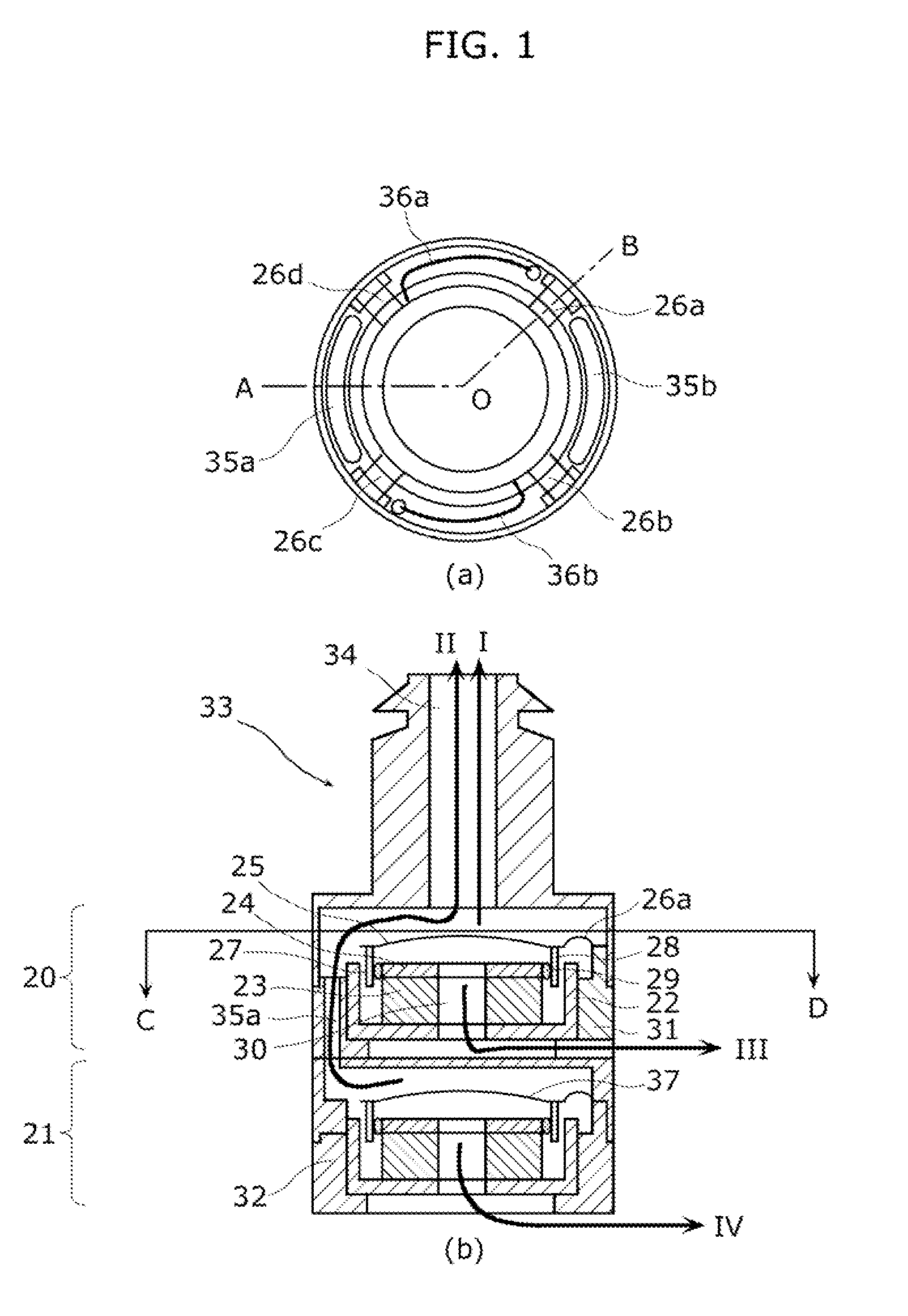
[0039]FIG. 1 is a diagram showing a speaker in Embodiment 1 of the present invention. Specifically, (a) in FIG. 1 is a transverse cross-sectional view of the speaker in the present embodiment. Furthermore, (b) in FIG. 1 is a vertical cross-sectional view of the speaker in the present embodiment. More specifically, (a) in FIG. 1 is a cross-sectional view of the speaker when cut along a line C-D of the vertical cross-sectional view shown in (b) in FIG. 1. Furthermore, (b) in FIG. 1 is a cross-sectional view of the speaker when cut along a line defined by A-O-B shown in the transverse cross-sectional view in (a) in FIG. 1.

[0040]As shown in FIG. 1, the speaker in the present embodiment includes a first unit 20, a second unit 21, a first frame 31, a second frame 32, and an acoustic port 33. In the present embodiment, each of the first unit 20 and the second unit 21 is an electrodynamic electro-acoustic transducer including a magnetic circuit.

[0041]The first unit 20 is disposed between th...

embodiment 2

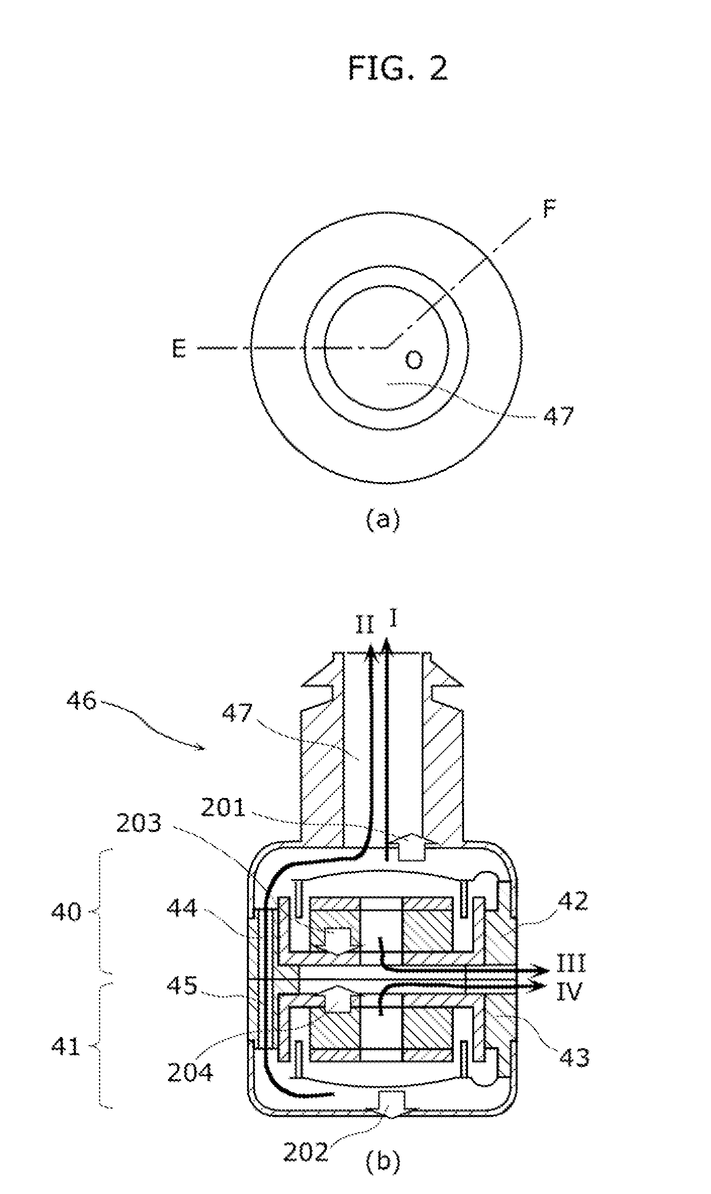
[0072]Next, Embodiment 2 of the present invention shall be described.

[0073]A significant difference between a speaker in the present embodiment and the speaker in Embodiment 1 described earlier lies in the arrangement direction of the two units. In Embodiment 1, the positional relationship of the magnetic circuit and the diaphragm with respect to the emission direction of the sound radiated from the acoustic port is the same for the first unit and the second unit. In other words, in Embodiment 1, in both the first unit and the second unit, the diaphragm and the magnetic circuit are arranged in sequence from the acoustic port-side.

[0074]On the other hand, in Embodiment 2, the two units are arranged such that the magnetic circuits are opposed. Specifically, the first unit and the second unit are arranged such that the bottom face of the magnetic circuit of the first unit and the bottom face of the magnetic circuit of the second unit face each other. Stated differently, the diaphragms ...

embodiment 3

[0093]Next, Embodiment 3 of the present invention shall be described.

[0094]The difference between a speaker in the present embodiment and the speaker in Embodiment 2 lies in the arrangement direction of the first unit and the second unit. Specifically, in Embodiment 2, the bottom faces of magnetic circuits of the respective units are arranged to face each other, whereas, in the present embodiment, the diaphragms of the respective units are arranged to face each other via a spacer 54.

[0095]Hereinafter, the speaker in Embodiment 3 shall be described with reference to the Drawings.

[0096]FIG. 4 is a diagram showing the speaker in Embodiment 3 of the present invention. Specifically, (a) in FIG. 4 is a plan view of the speaker in the present embodiment. Furthermore, (b) in FIG. 4 is a vertical cross-sectional view of the speaker in the present embodiment. More specifically, (b) in FIG. 4 is a cross-sectional view of the speaker when cut along a line defined by G-O-H shown in the plan view...


PUM


Abstract

A speaker capable of suppressing deterioration of acoustic efficiency while allowing miniaturization of the speaker includes a first unit (20) and a second unit (21) each of which outputs sound. The first unit (20) includes: a diaphragm (25) which vibrates back and forth to radiate sound; and plural suspensions (26a, 26b, 26c, 26d) which support, at different positions, an outer periphery of the diaphragm (25). At least one of air passages (35a, 35b) for channeling sound from the second unit (21) to the outside is provided between the plural suspensions (26a, 26b, 26c, 26d).

Description

TECHNICAL FIELD[0001]The present invention relates to a small speaker, particularly an ultra-small speaker called a receiver, and to a device including the small speaker.BACKGROUND ART[0002]Along with the popularization of portable music players, recent years have seen heavy use of earphones and headphones for easy music reproduction and enjoyment indoors and outdoors. Furthermore, with the advancement of an aging society, the demand for hearing aids has increased and increased use of receivers, which are ultra-small speakers used in sound reproduction in hearing aids, is expected.[0003]Among earphones intended primarily for such music reproduction or hearing aid receivers, inner ear earphones or receivers which are inserted into the external auditory canal of the ears are widely used. Taking into consideration the wearing comfort of a user, it is preferable that the configuration of such an inner ear earphone or receiver be compact. In particularly, for hearing aids that a user wea...

Claims


Application Information

Patent Timeline
Patent Type & Authority Applications(United States)
IPC IPC(8): H04R25/00H04R1/20H04R1/00
CPCH04R1/10H04R9/063H04R7/20H04R1/1016H04R25/00
Inventor SAIKI, SHUJI
Owner PANASONIC CORP
Why Eureka
Try Eureka