Cartridge and image forming apparatus
- Summary
- Abstract
- Description
- Claims
- Application Information
AI Technical Summary
Benefits of technology
Problems solved by technology
Method used
Image

Examples
first embodiment
[0036](General structure of Electrophotographic Image Forming Apparatus)
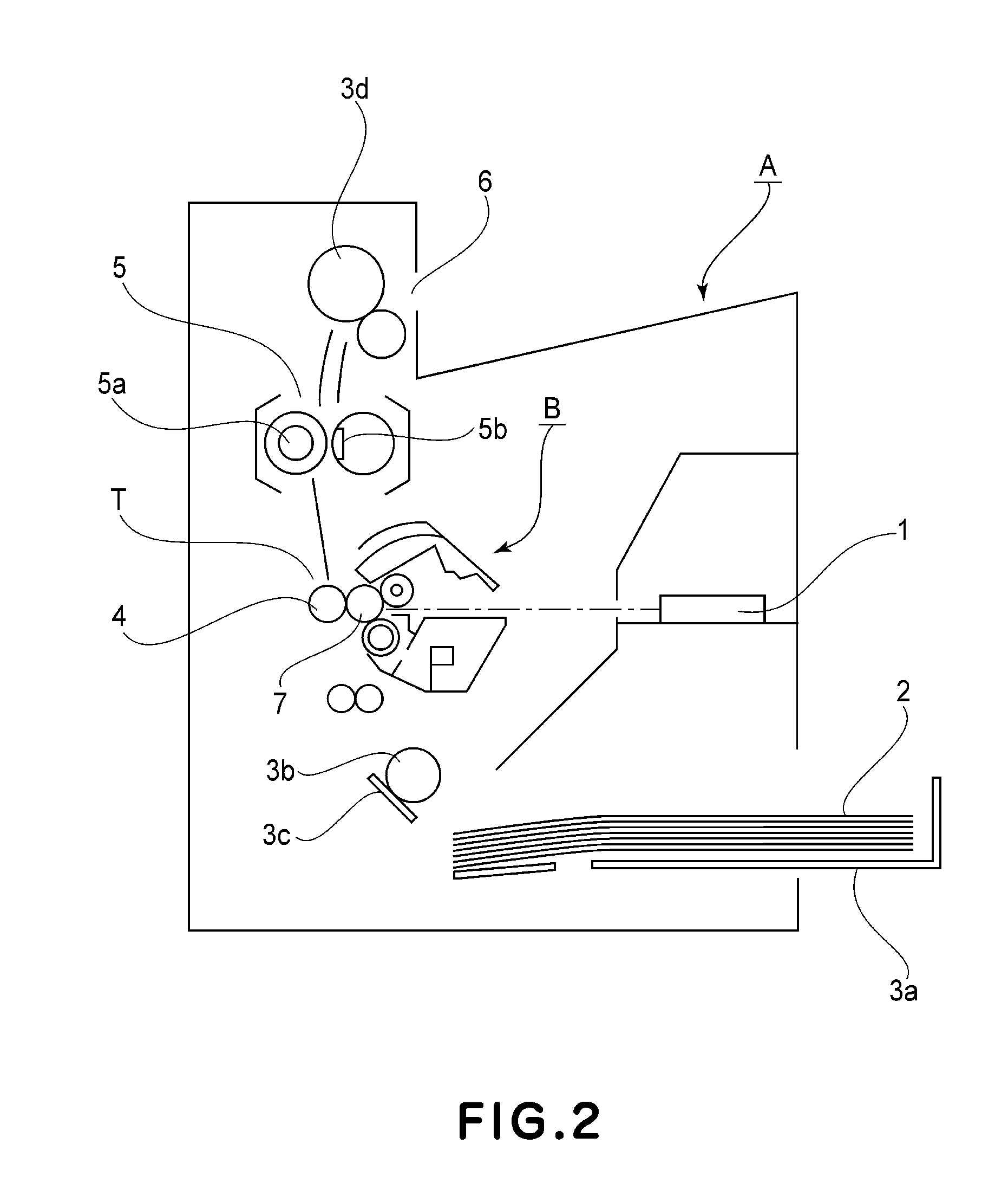
[0037]First, a general structure of the electrophotographic image forming apparatus will be described with reference to FIG. 2. FIG. 2 is a schematic sectional view of the electrophotographic image forming apparatus in this embodiment. More specifically, FIG. 2 is a schematic sectional view of a laser beam printer as an example of the image forming apparatus.
[0038]As shown in FIG. 2, in the image forming apparatus (laser beam printer) A in this embodiment, information light on the basis of image information is emitted from an optical system 1 as an optical means to a drum-like electrophotographic photosensitive member (image bearing member), hereinafter referred to as a photosensitive drum) 7. Thus, an electrostatic latent image is formed on the photosensitive drum 7. This electrostatic latent image is developed with a developer (hereinafter referred to as a toner), so that a toner image is formed.
[0039]On the o...
second embodiment
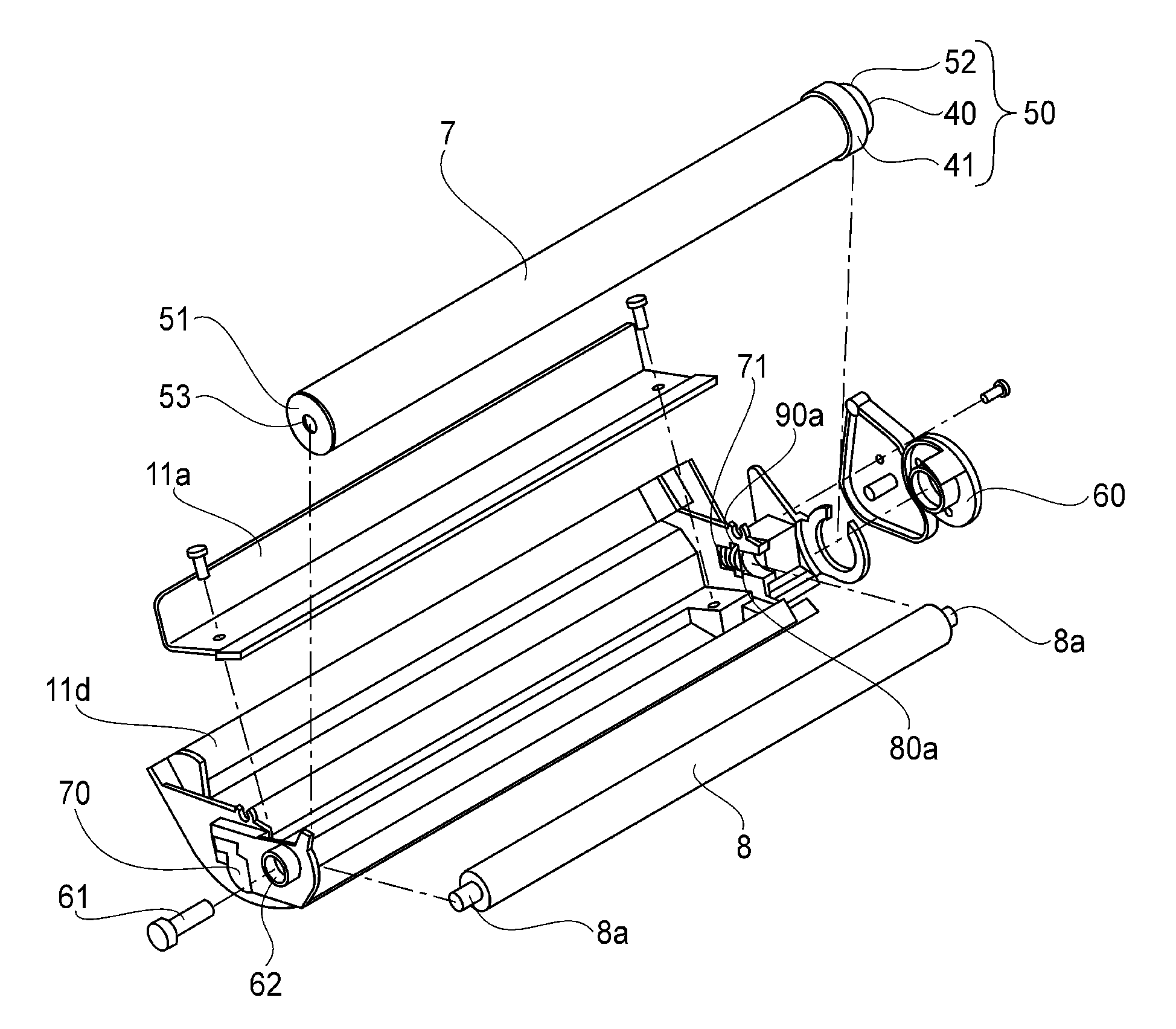
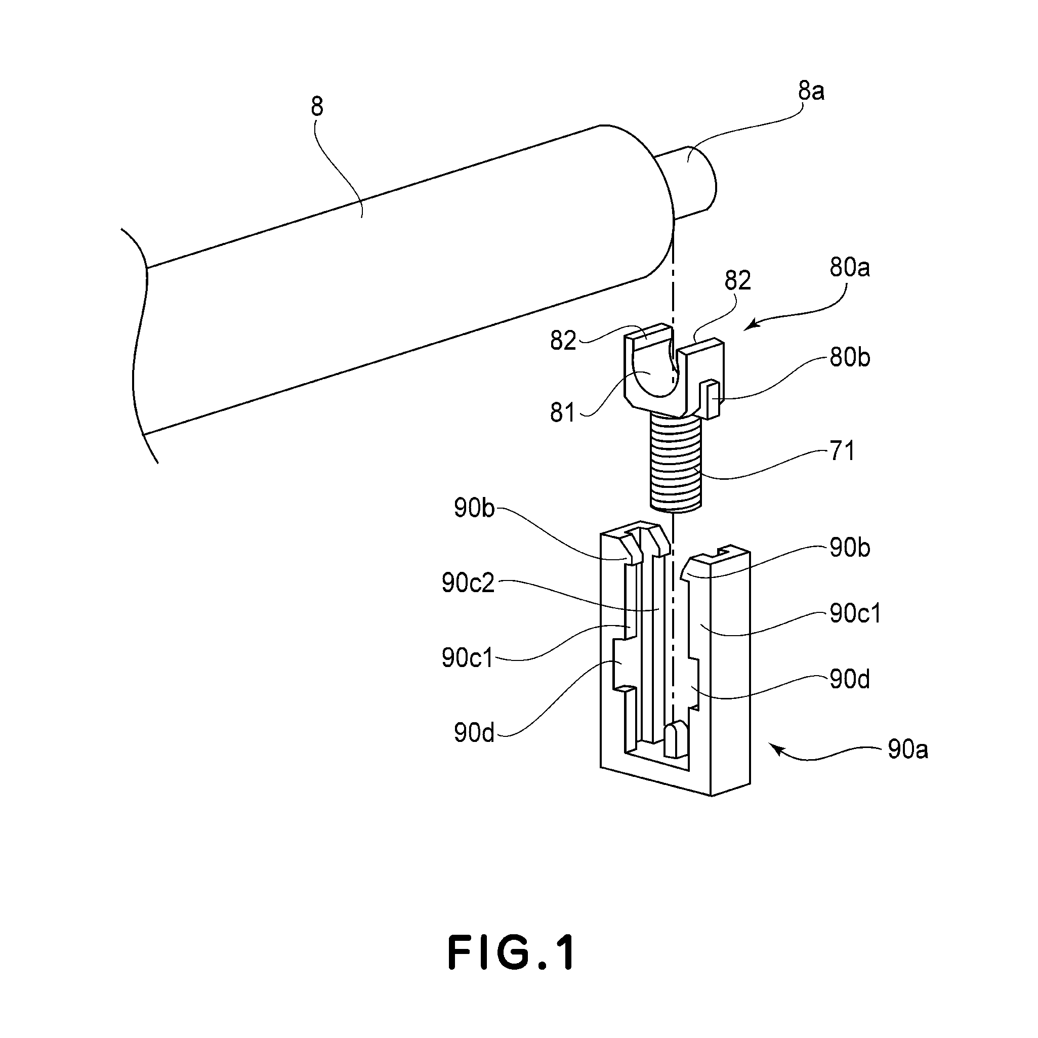
[0081]The bearing member supporting structure of the drum supporting frame in this embodiment will be described with reference to FIGS. 7 and 8. Constituent elements similar to those in First Embodiment are represented by the same reference numerals or symbols. Parts (a), (b) and (c) of FIG. 7 are a side view and sectional views of the supporting structure for the bearing member in this embodiment. Here, (a) of FIG. 7 is the side view of the supporting structure at the first position in which the charging roller 8 is contacted to the photosensitive drum 7, (b) of FIG. 7 is the sectional view of the supporting structure at the first position, and (c) of FIG. 7 is the sectional view of the supporting structure at the second position in which the charging roller 8 is separated from the photosensitive drum 7. FIG. 8 is a perspective view of the bearing member in this embodiment.
[0082]Here, the supporting portion 90a is provided with a frame-side longitudinal direction movement preventin...
third embodiment
[0088]The bearing member supporting structure of the drum supporting frame in this embodiment will be described with reference to FIGS. 9, 10 and 11. Constituent elements similar to those in First Embodiment are represented by the same reference numerals or symbols. FIG. 9 is a schematic view for illustrating the supporting structure for the bearing member in this embodiment. Parts (a), (b) and (c) of FIG. 10 are a side view and sectional views of the supporting structure for the bearing member in this embodiment. Here, (a) of FIG. 10 is the side view of the supporting structure at the first position in which the charging roller 8 is contacted to the photosensitive drum 7, (b) of FIG. 10 is the sectional view of the supporting structure at the first position, and (c) of FIG. 10 is the sectional view of the supporting structure at the second position in which the charging roller 8 is separated from the photosensitive drum 7. FIG. 11 is a perspective view of the supporting structure f...
PUM
| Property | Measurement | Unit |
|---|---|---|
| Electrical conductor | aaaaa | aaaaa |
Abstract
Description
Claims
Application Information
 - Generate Ideas
- Intellectual Property
- Life Sciences
- Materials
- Tech Scout
- Unparalleled Data Quality
- Higher Quality Content
- 60% Fewer Hallucinations
Browse by: Latest US Patents, China's latest patents, Technical Efficacy Thesaurus, Application Domain, Technology Topic, Popular Technical Reports.
© 2025 PatSnap. All rights reserved.Legal|Privacy policy|Modern Slavery Act Transparency Statement|Sitemap|About US| Contact US: help@patsnap.com