
Fuel cell system and method of controlling fuel cell system

Active Publication Date: 2012-03-22
TOYOTA JIDOSHA KK
View PDF0 Cites 12 Cited by
  • Summary
  • Abstract
  • Description
  • Claims
  • Application Information

AI Technical Summary

Benefits of technology

[0014]The invention provides a fuel cell system that prevents the output voltage of a fuel cell from increasing to the open circuit voltage after operation of a system that includes the fuel cell is stopped, thereby suppressing deterioration of a catalyst in the fuel cell, and a method of controlling the fuel cell system.
[0020]According to the fuel cell system of the invention and the control method thereof, after the operation of the fuel cell system is stopped, the DC / DC converter continues to be driven, and the high potential avoidance control is thereby performed for the predetermined time to control the voltage of the fuel cell below the high potential avoidance voltage lower than the open circuit voltage. Thus, the output voltage of the fuel cell can be restrained from rising to the open circuit voltage after the stoppage of the operation of the system. As a result, the catalyst in the fuel cell can be restrained from deteriorating.
[0021]Further, in the aforementioned control method, control of lowering the voltage command for the DC / DC converter from a first value corresponding to the high potential avoidance voltage to a second value may be performed during the high potential avoidance control after the inputting of the system operation stop command to the control unit. According to the control method, electric power generation in the fuel cell can be promoted to accelerate the consumption of the remaining oxygen, and the time for driving the DC / DC converter after the stoppage of the operation of the system can be shortened. Thus, the time from a timing when the operation of the system is stopped to a timing when the DC / DC converter is shut down and a system main relay included in the fuel cell system is opened can be made short.

Problems solved by technology

As a result, there arises a problem in that the electromotive force of each unit fuel cell rises to the open circuit voltage.
However, this publication does not offer any solution to the necessity of restraining the output voltage of the fuel cell from rising to the open circuit voltage after the stoppage of the operation of the system including the fuel cell.

Method used


Image

  • Fuel cell system and method of controlling fuel cell system
  • Fuel cell system and method of controlling fuel cell system
  • Fuel cell system and method of controlling fuel cell system

Examples


Embodiment Construction

[0028]The embodiment of the invention will be described hereinafter in detail with reference to the accompanying drawings. In this description, concrete shapes, materials, values, directions, and the like are examples to facilitate understanding of the invention, and may be changed in accordance with the use, purpose, specification, and the like, as appropriate.

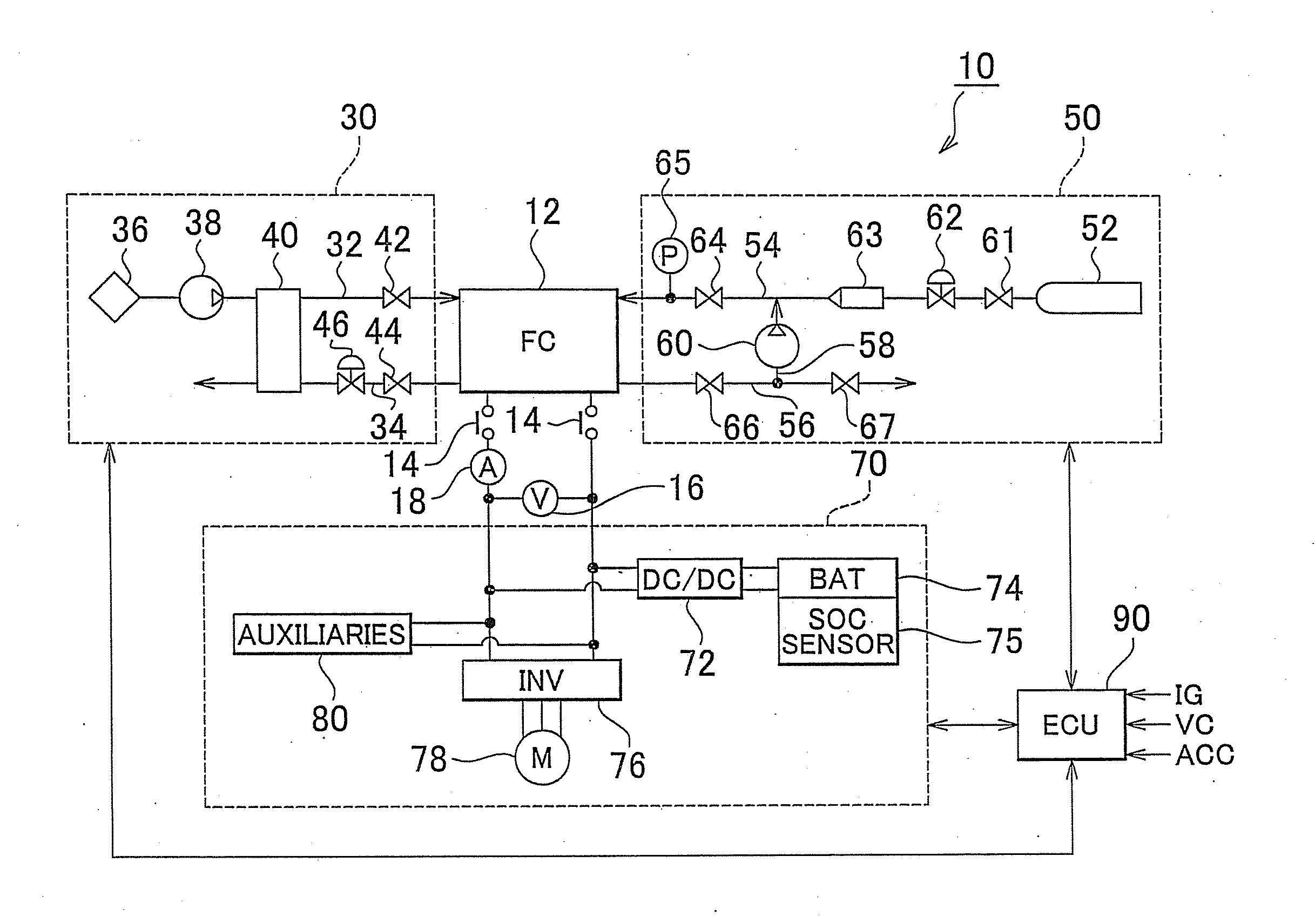
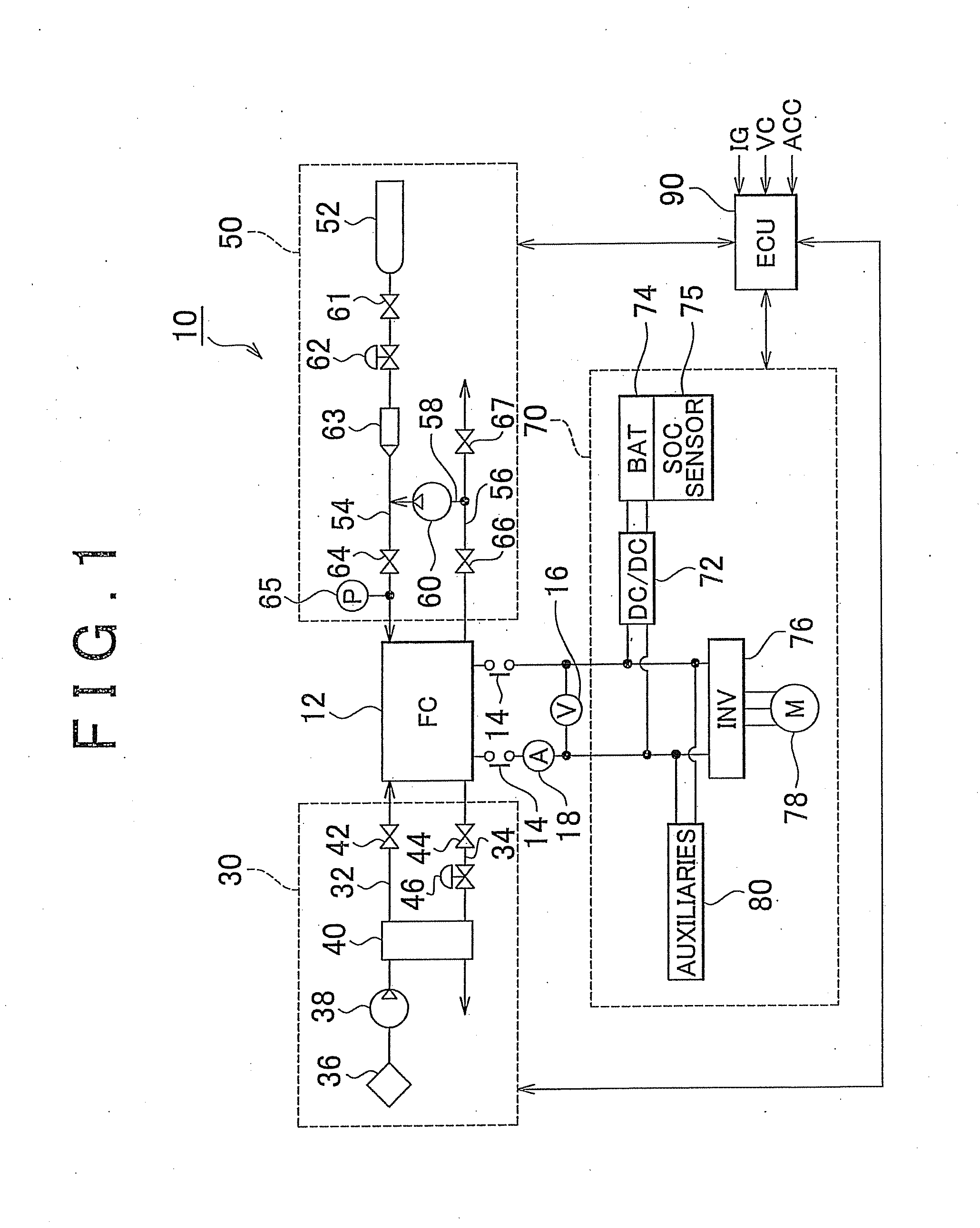
[0029]FIG. 1 is an overall system diagram showing an example in which a fuel cell system 10 according to an embodiment of the invention is employed as an on-vehicle electric power supply system of a fuel-cell-powered vehicle. The fuel cell system 10 includes a fuel cell stack (a fuel cell) 12 that is supplied with a fuel as and an oxidizing gas to generate electric power, an air supply system 30 for supplying the fuel cell stack 12 with oxygen in air as the oxidizing gas, a hydrogen supply system 50 for supplying the fuel cell stack 12 with hydrogen as the fuel gas, an electric power system 70 for controlling the charge / disch...


PUM


Abstract

A fuel cell system is equipped with a fuel cell, a DC / DC converter that is electrically connected to the fuel cell, and a control unit that controls the supply of a fuel gas and an oxidizing gas to the fuel cell and issues a voltage command to and drives the DC / DC converter to perform high potential avoidance control of restraining an output voltage of the fuel cell from exceeding a high potential avoidance voltage lower than an open circuit voltage. The control unit continues to drive the DC / DC converter so as to perform the high potential avoidance control for a predetermined time after stopping supplying the fuel cell with hydrogen and air in response to the inputting of a system operation stop command.

Description

BACKGROUND OF THE INVENTION[0001]1. Field of the Invention[0002]The invention relates to a fuel cell system and a method of controlling the fuel cell system. In particular, the invention relates to a fuel cell system that controls the output voltage of a fuel cell by means of a DC / DC converter, and a control method of the fuel cell system.[0003]2. Description of the Related Art[0004]A conventional fuel cell generates electric power through an electrochemical reaction of hydrogen and oxygen in air. The fuel cell is a clean electric power generation unit that does not discharge carbon dioxide, which is considered to be a cause for global warming. The fuel cell is expected as an electric power supply unit for an electric vehicle employing a motor as a motive power source.[0005]In general, a fuel cell is constructed as a cell stack that includes a multitude of unit fuel cells, each of which generates electricity, connected in series and laminated on one another. Each of the unit fuel ce...

Claims


Application Information

Patent Timeline
IPC IPC(8): H01M8/04
CPCH01M8/04223H01M8/04552Y02E60/50H01M8/04873H01M16/003H01M8/04753H01M8/04228H01M8/04303H01M8/04225
Inventor YOSHIDA, MICHIO
Owner TOYOTA JIDOSHA KK
Learn More