

Apparatus for reducing hydrocarbon emission of internal combustion engine
- Summary
- Abstract
- Description
- Claims
- Application Information
AI Technical Summary
Benefits of technology
Problems solved by technology
Method used
Image

Examples
first embodiment
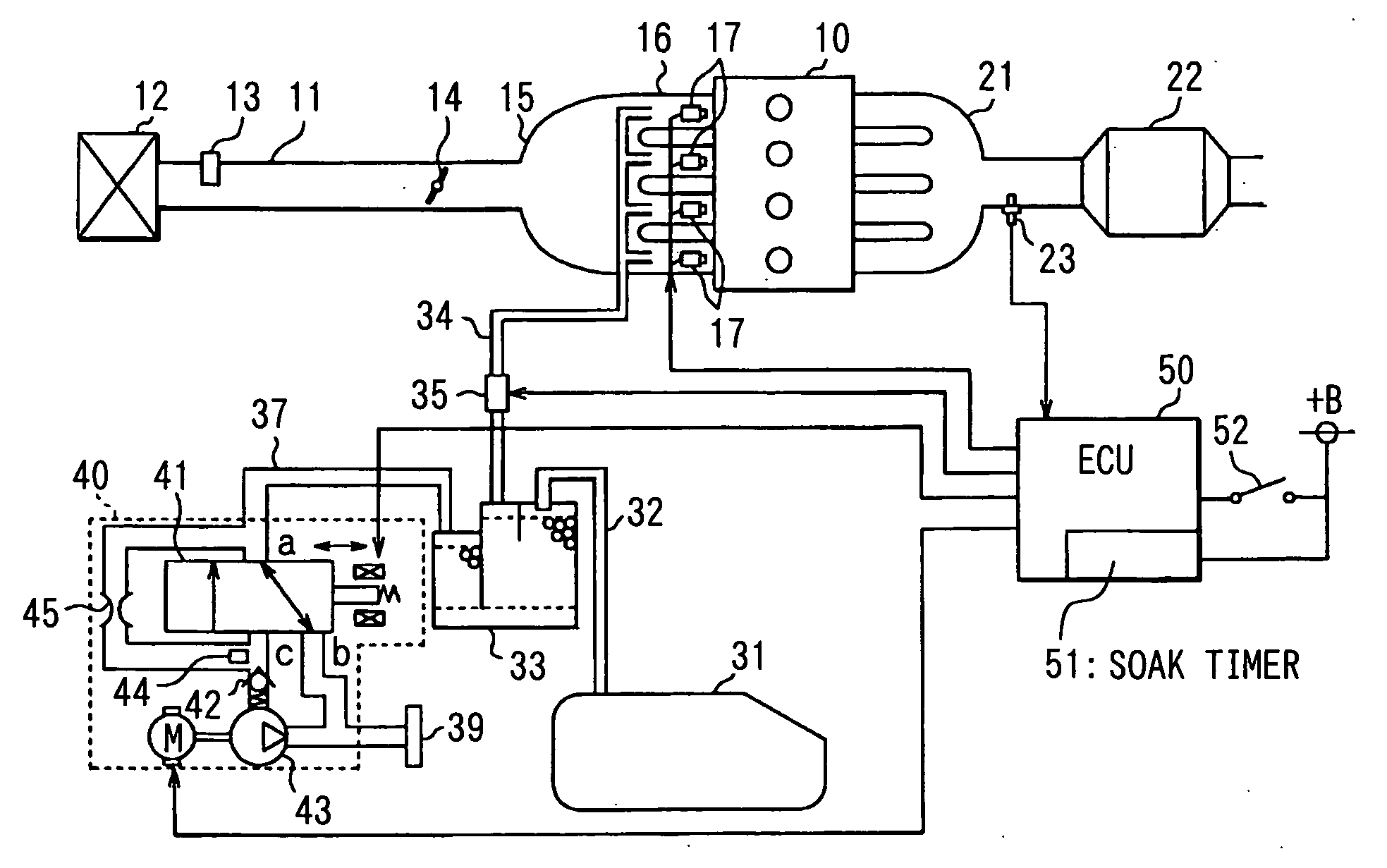
[0027] The present invention is applied to a four-cylinder gasoline injection engine. FIG. 1 is a schematic view showing an engine control system according to a
[0028] Referring to FIG. 1, an air-cleaner 12 is disposed at an inlet of an intake pipe 11, and airflow meter 13 for measuring the amount of air passing through the intake pipe 11 is disposed downstream of the air-cleaner 12 in the intake pipe 11. The airflow meter 13 is provided with an intake air temperature sensor (not shown). A throttle valve 14 is provided downstream of the airflow meter 13, which is controlled an opening degree thereof by a DC motor and the like. A surge tank 15 is connected with the intake pipe 11 downstream of the throttle valve 14. An intake manifold 16 for introducing an air into the each cylinder is connected with the surge tank 15. A fuel injector 17 is provided at each intake port of the intake manifold 16. An intake passage is comprised of the intake pipe 11, the surge tank 15 and the intake man...
second embodiment
[0053] the present invention is described herein after.
[0054] Referring to FIG. 7, an air-cleaner 312 is disposed at an inlet of an intake pipe 311, and airflow meter 313 for measuring the amount of air passing through the intake pipe 311 is disposed in the intake pipe 311, the airflow meter 313 being disposed downstream of the air-cleaner 312. The airflow meter 313 is provided with an intake air temperature sensor (not shown) therein. A throttle valve 314 is provided downstream of the airflow meter 313, which is controlled an opening degree thereof by a throttle actuator 314a such as an DC motor and the like. A surge tank 315 is connected with the intake pipe 311 downstream of the throttle valve 314. An intake manifold 316 for introducing an air into the each cylinder is connected with the surge tank 315. A fuel injector 317 is provided at each intake port of the intake manifold 316. An intake passage is comprised of the intake pipe 311, the surge tank 315 and the intake manifold 3...
PUM
 Abstract
Description
Claims
Application Information