Apparatus for premounting of locking elements to a panel

a technology for pre-mounting and locking elements, which is applied in the field of pre-mounting of locking elements to panels, can solve the problems of disadvantageous slippage of locking elements, poor installation effect of locking elements, and difficulty in proper laying of panels with latching engagement into the latching recess, etc., and achieves the effect of easy installation and inexpensive production by machin

Inactive Publication Date: 2012-03-29
AKZENTA PANEELE PROFILE GMBH
View PDF0 Cites 96 Cited by
  • Summary
  • Abstract
  • Description
  • Claims
  • Application Information

AI Technical Summary

Benefits of technology

[0009]The object of the invention is to provide a latching element, also referred to as a locking element, of the kind set forth in the opening part of this specification, which effectively counteracts the above-indicated disadvantages, and aims to afford a panel which can be easily installed, with an additional locking element, which can be inexpensively produced by machine, more specifically by means of a method and an apparatus for automatically pre-mounting the locking element to an edge of the panel, in which respect industrial mounting is to be possible.

Problems solved by technology

For that purpose, to produce a spring energy, the latching tongue will be applied against the spring force of the latching tongue as far as possible in a direction towards the insertion portion, which detrimentally requires a correspondingly high level of application force.
In addition, the locking element can disadvantageously slip due to the handling procedure involved when laying the panels, whereby proper laying of the panels with the latching engagement into the latching recess is at least rendered more difficult.

Method used


Image

  • Apparatus for premounting of locking elements to a panel
  • Apparatus for premounting of locking elements to a panel
  • Apparatus for premounting of locking elements to a panel

Examples


Embodiment Construction

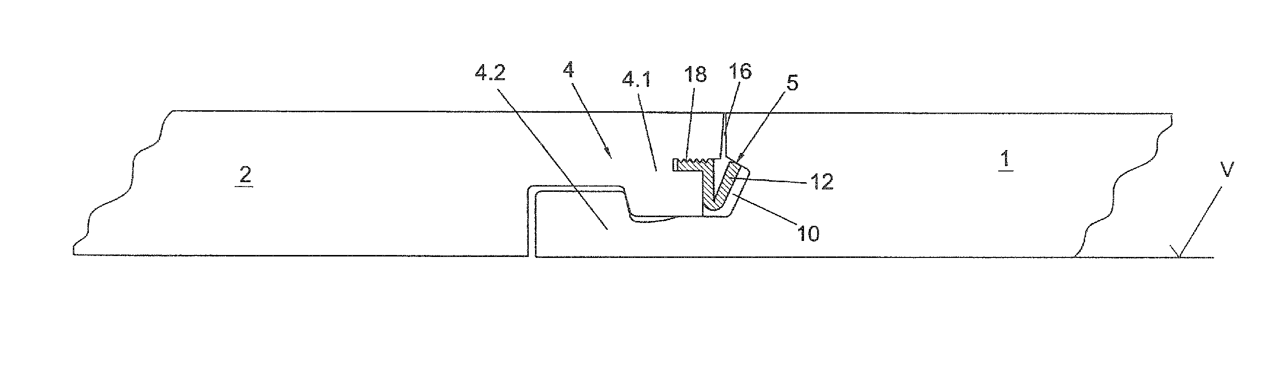
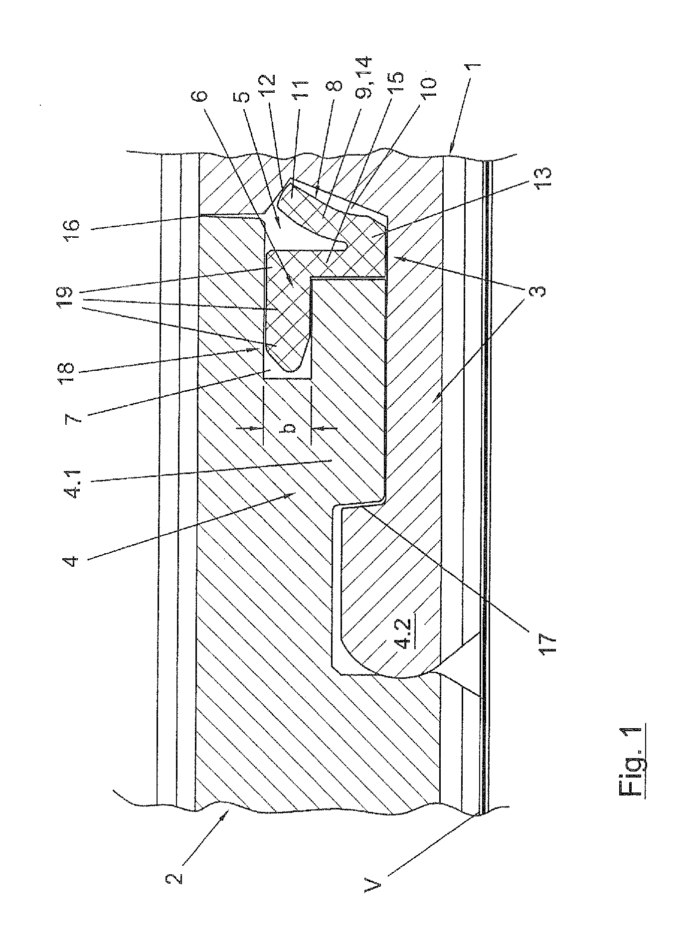
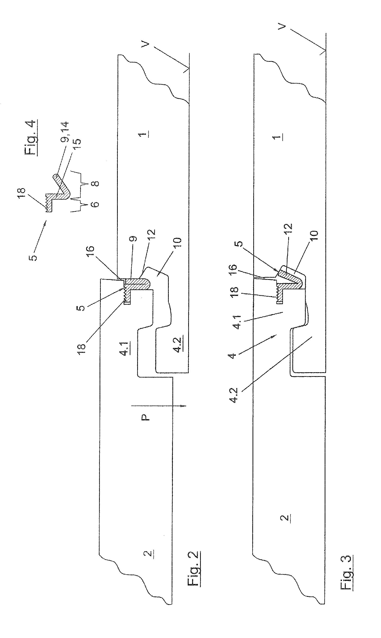
[0142]FIG. 1 shows a part of a cross-sectional view of two panels 1, 2 of a quadrangular, plate-shaped configuration, wherein the illustrated part reproduces a fixing system 3 having a locking element 5, by way of which the two panels 1, 2 are connected together and locked together at their edges or narrow sides by means of a hook connection 4 and a locking element 5 according to the invention. The hook connection 4 has two hooks 4.1, 4.2 which in the locking position are hooked into each other in such a way that the panels 1, 2 cannot be displaced horizontally relative to each other in the position which here is horizontal.

[0143]The locking element 5 is inserted with a portion in the form of an insertion portion 6 in a locking groove 7 which extends in the longitudinal direction of the edges of the panel 2, which edges extend in the plane of the drawing. The locking element 5 also has a portion in the form of a locking portion 8 with a resilient latching tongue 9 which is latched i...


PUM

PropertyMeasurementUnit
angleaaaaaaaaaa
angleaaaaaaaaaa
thicknessesaaaaaaaaaa

Abstract

The apparatus mounts a locking element into a groove in an edge of a panel. An advance device feeds a stream of locking elements to a pressing device which mounts the locking elements into the groove on the edge of the panel. The locking elements are fed from a line of locking elements stored on a reel. A separating device cuts the line of locking elements into individual locking elements. The separating device is positioned either upstream of the advancing device or immediately upstream of the pressing device. When the separating device is immediately upstream of the pressing device, a spring is used to flex the stream during the short stoppage when the separating device separates individual locking elements from the line of locking elements.

Description

CROSS-REFERENCE TO RELATED APPLICATIONS[0001]This is a Divisional application of U.S. patent application Ser. No. 12 / 064,945 filed Mar. 10, 2008 which was a National Stage Entry of International Application No. PCT / EP2006 / 011684 filed Dec. 6, 2006, which claimed the priority of DE 10 2006 002 027.8 filed Jan. 13, 2006, DE 10 2006 002 028.6 filed Jan. 13, 2006, and DE 10 2006 011 887.1 filed Mar. 15, 2006, the priorities of these applications are claimed and these applications are incorporated herein by reference.FIELD OF THE INVENTION[0002]The invention concerns a locking element, panel with separate locking element for locking panels, method of installing a panel covering comprising panels with locking elements and a method and apparatus for pre-mounting one or more locking elements to a panel.[0003]The invention concerns a locking element for a fixing system for quadrangular plate-shaped panels wherein the locking element is provided with an insertion portion for insertion of the ...

Claims


Application Information

Patent Timeline
Patent Type & Authority Applications(United States)
IPC IPC(8): E04C2/38E04B1/38E04C2/40
CPCB27M3/0066B27M3/04E04F15/02E04F2201/0115E04F2201/0123E04F2201/0153Y10T29/49616E04F2201/0535E04F2201/0547E04F2201/0588F16B5/0056Y10T29/49623Y10T29/49629E04F2201/0176
Inventor HANNIG, HANS-JUERGEN
Owner AKZENTA PANEELE PROFILE GMBH
Why Eureka
Try Eureka