Electric vehicle

Inactive Publication Date: 2012-03-29
TOYOTA IND CORP
View PDF0 Cites 119 Cited by
  • Summary
  • Abstract
  • Description
  • Claims
  • Application Information

AI Technical Summary

Benefits of technology

[0012]Thus, the discharge of the auxiliary battery can be suppressed.
[0013]According to the present invention, when a battery for driving a vehicle driving motor is

Problems solved by technology

However, when a charging station provided for a public facility etc., an unspecific electric vehicle may be charged.
Since pow

Method used


Image

  • Electric vehicle
  • Electric vehicle
  • Electric vehicle

Examples


Embodiment Construction

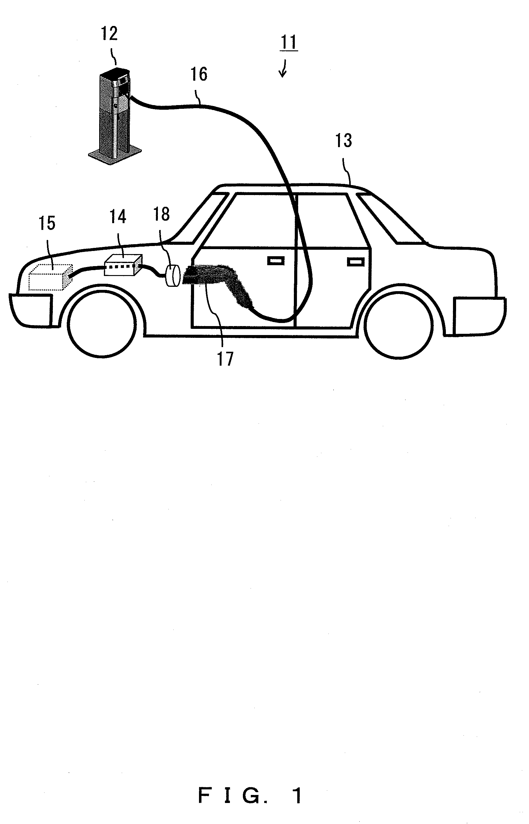
[0020]FIG. 1 illustrates a vehicle charging system.

[0021]In a vehicle charging system 11 illustrated in FIG. 1, a charging station 12 supplies power to an electric vehicle 13 such as a hybrid car, an electric car, etc.

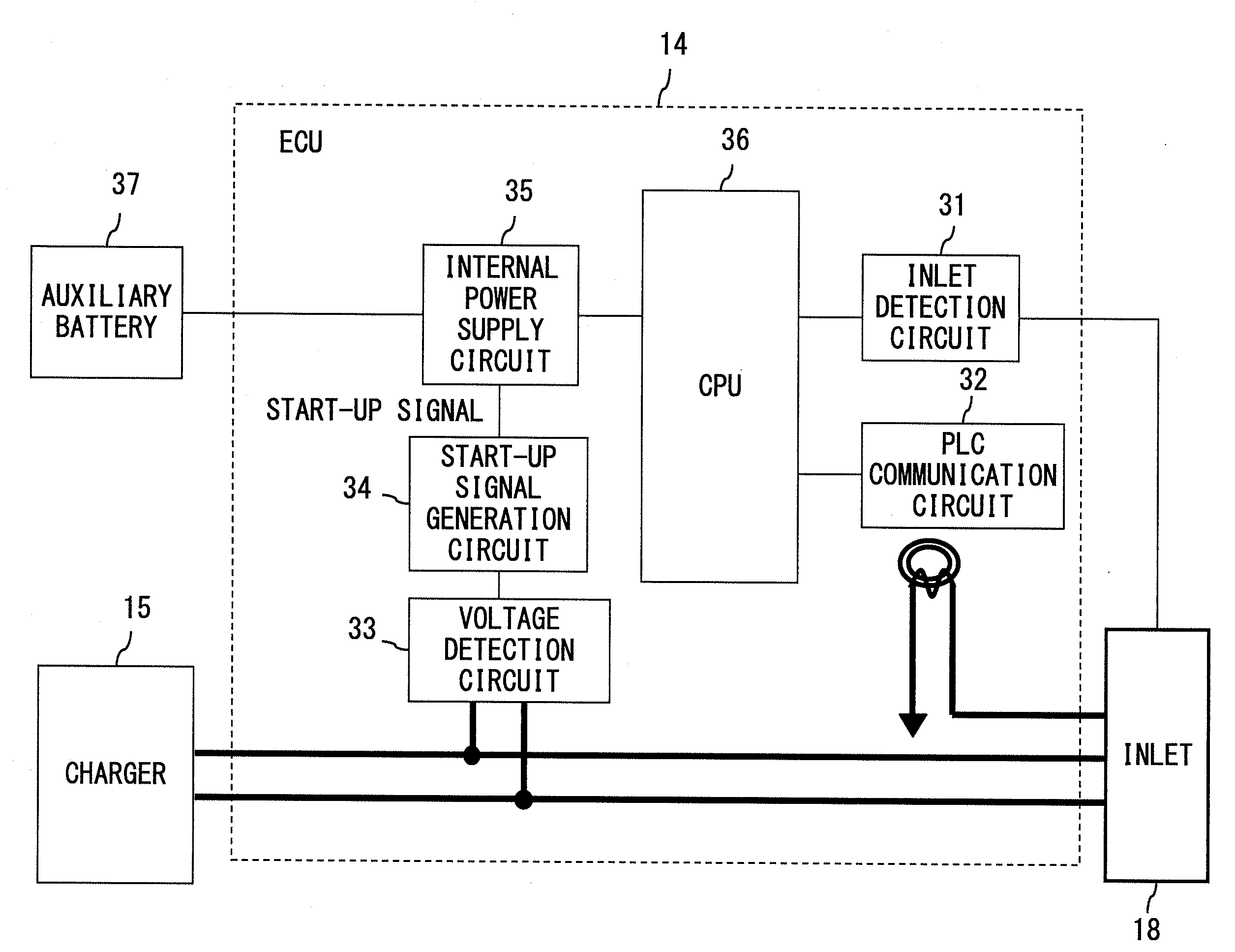
[0022]The electric vehicle 13 according to the present embodiment includes an ECU 14 for controlling a charging process performed when a battery for driving a vehicle driving motor is charged by electric power supplied from the charging station 12, and a charger 15 for charging the battery by the electric power supplied from the charging station 12.

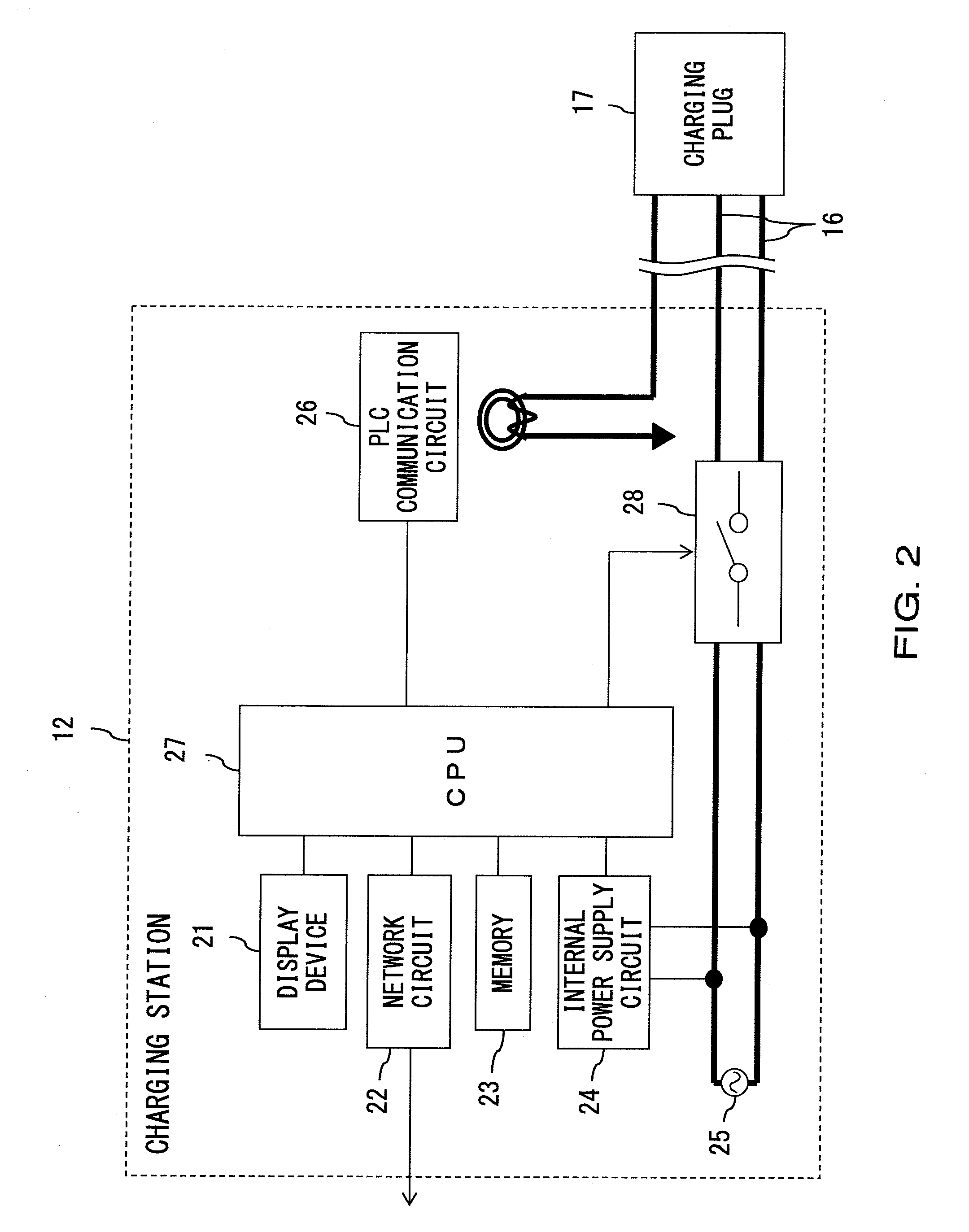
[0023]When a user inserts a charging plug 17 provided at the end portion of an AC cable 16 extending from the charging station 12 into an inlet 18 electrically connected to the charger 15, and sets the charging start timing in the charging station 12, electric power is supplied from the charging station 12 to the electric vehicle 13 with the charging start timing.

[0024]FIG. 2 is a configuration of the charging station 12. Th...


PUM


Abstract

An electric vehicle suppresses the discharge of an auxiliary battery for supplying electric power to a control circuit for controlling a charging process while performing timer-charging. When the charging start timing set by a user comes after specified elapsed time, the power supply from an internal power supply circuit 35 to a CPU 36 etc. is stopped until the power supply is started from a charging station 12 to an electric vehicle 13. When the stopped power supply is started, the power supply from the internal power supply circuit 35 to the CPU 36 etc. is resumed.

Description

TECHNICAL FIELD[0001]The present invention relates to an electric vehicle for charging a battery for drive of a vehicle driving motor by electric power supplied from a charging station.BACKGROUND ART[0002]In view of environment problems, an electric vehicle loaded with a vehicle driving motor such as an electric car, a plug-in hybrid car, etc. has received widespread attention (refer to, for example, the patent document 1 or 2).[0003]The electric vehicle has, for example, the following charging start sequence for a battery to drive a motor.1) A user inserts a charging plug provided for the end portion of an AC cable extending from a charging station into an inlet connected to the charger of the electric vehicle.2) A start-up signal is transmitted to an ECU (hereafter referred to as a control circuit) for control of the charging process of the electric vehicle from the charging station through a communication line associated with the AC cable.3) The start-up signal activates the cont...

Claims


Application Information

Patent Timeline
IPC IPC(8): H02J7/02H02J7/00
CPCB60L11/1816Y04S30/14B60L11/1848B60L11/185B60L2230/40G07F15/005G07F17/0021H01M10/44Y02T10/7005Y02T10/7088Y02T90/128Y02T90/14Y02T90/163Y02T90/169Y02T90/121B60L11/1846B60L53/14B60L53/65B60L53/665B60L53/11B60L53/68Y02T10/7072Y02T10/70Y02T90/12Y02T90/167Y02T90/16Y02E60/10H02J7/04H02J7/00
Inventor NAKASHIMA, YUTAKA
Owner TOYOTA IND CORP
Why Eureka
Try Eureka