Image forming apparatus
- Summary
- Abstract
- Description
- Claims
- Application Information
AI Technical Summary
Benefits of technology
Problems solved by technology
Method used
Image
Examples
example 1
of Drum Axle Fixing Structure
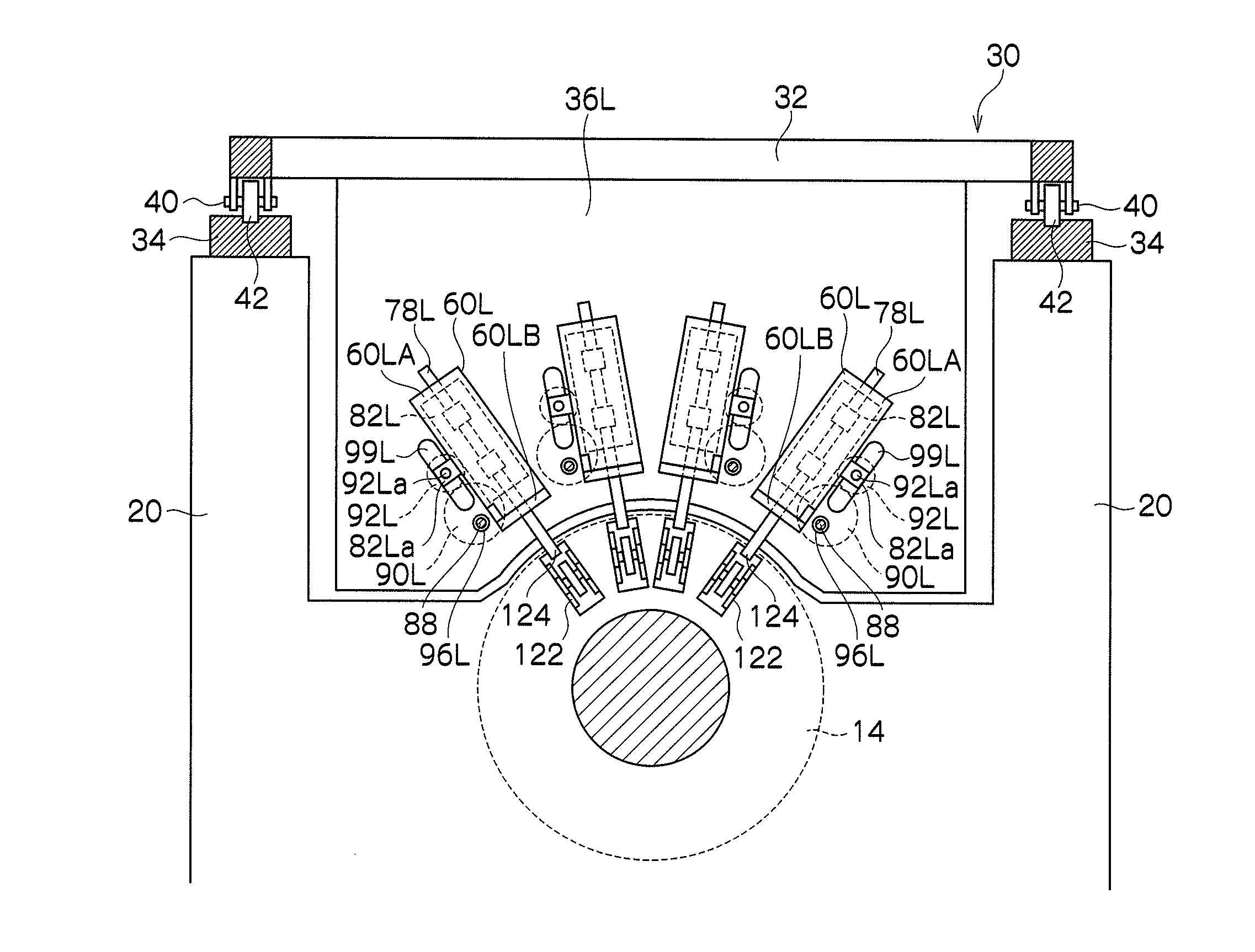
[0208]FIG. 18 is a cross-sectional diagram showing a first example of a drum axle fixing structure. Here, the description takes the image formation drum 14 as an example, but an axle fixing structure of the same sort is also adopted for other drums and rollers, such as the transfer drums 26, 28, and the like.
[0209]As shown in FIG. 18, a step section (recess section) 134 which accommodates a bearing 132 is formed in an opening section 130 of the main body frame 20, and a ring-shaped bearing 132 is provided in this step section 134. The bearing 132 is fixed by heat and pressure fitting into the step section 134 of the main body frame 20. The bearing 132 functions as a bearing for rotatably supporting the rotating axle (drum axle) 140 of the image formation drum 14. A screw section 144 is formed in the end portion of the drum axle 140 which passes through the bearing 132. A fastening screw 146 is fastened into this screw section 144, and an inner ring 133 o...
example 2
of Drum Axle Fixing Structure
[0211]FIG. 19 is a diagram showing a second example of a drum axle fixing structure. In FIG. 19, one end portion (the left-hand side in FIG. 19) of the rotating axle 140 of the image formation drum 14 is installed on the main body frame 20 via a bearing 152. The bearing 152 is fixed by heat and pressure fitting to the main body frame 20.
[0212]The other end portion of the image formation drum 14 (the right-hand side in FIG. 19) is installed on the main body frame 20 via a bearing 154. The bearing 154 is arranged in the opening section 160 of the main body frame 20, and the drum axle 141 is supported rotatably in this bearing 154. A gear 143 for transmitting drive force for causing the image formation drum 14 to rotate is provided in the end portion of the drum axle 141. This gear 143 corresponds to a gear wheel which is indicated by reference numeral 520 in FIG. 22.
[0213]Furthermore, as shown in FIG. 19, a sleeve 162 is arranged to abut against the outer ...
modification example
[0289]In the embodiments described above, an inkjet recording apparatus which conveys paper by drum conveyance is described by way of an example, but the paper conveyance device is not limited to this. For example, the present invention can also be applied similarly to an inkjet recording apparatus which uses belt conveyance or an inkjet recording apparatus which uses roller conveyance. In this case, an axle fixing structure similar to that of the image formation drum is adopted for the rollers about which the belt is wrapped, and the paper conveyance rollers.
PUM
 Abstract
Description
Claims
Application Information
 - R&D
- Intellectual Property
- Life Sciences
- Materials
- Tech Scout
- Unparalleled Data Quality
- Higher Quality Content
- 60% Fewer Hallucinations
Browse by: Latest US Patents, China's latest patents, Technical Efficacy Thesaurus, Application Domain, Technology Topic, Popular Technical Reports.
© 2025 PatSnap. All rights reserved.Legal|Privacy policy|Modern Slavery Act Transparency Statement|Sitemap|About US| Contact US: help@patsnap.com


