Inkjet image forming apparatus, method of designing same and method of improving image formation quality

a technology of inkjet image and forming apparatus, which is applied in the direction of printing, other printing apparatus, etc., can solve the problems of relative vibration prone to occur between the liquid ejection head and the image formation receiving medium, and achieve the effect of improving the non-uniformity of vibration, improving the effect of vibration quality, and facilitating the change of components

Active Publication Date: 2011-09-29
FUJIFILM CORP
View PDF4 Cites 4 Cited by
  • Summary
  • Abstract
  • Description
  • Claims
  • Application Information

AI Technical Summary

Benefits of technology

[0049]In order to attain an object described above, another aspect of the present invention is directed to a method of improving image formation quality of an inkjet image forming apparatus including a liquid ejection head having an ejection surface in which a plurality of nozzles are arranged two-dimensionally, a scanning device which conveys at least one of the liquid ejection head and an image formation receiving medium on which liquid ejected from the plurality of nozzles is deposited, to cause relative movement between the image formation receiving medium and the liquid ejection head in a first direction, a drive force generating device which generates drive force for driving the scanning device, and a meshing transmission mechanism which transmits the drive force generated by the drive force generating device to the scanning device by a meshing mechanism, the method comprising the steps of: obtaining information indicating a spatial period obtained by converting a pitch of meshing teeth of the meshing transmission mechanism to an amount of the relative movement in the first direction on the image formation receiving medium; acquiring information indicating an offset distance in the first direction of a pair of nozzles which form dots that are mutually adjacent in a second direction perpendicular to the first direction on the image formation receiving medium, of the plurality of nozzles arranged two-dimensionally; and modifying the pitch of the meshing teeth so as to satisfy relationship of OSy≈k×Pv (where k is a natural number) when Pv represents the obtained spatial frequency and OSy represents the acquired offset distance.
[0050]In general, there is little scope for modification in the design of a nozzle arrangement, and in many cases it is easier to change the components or the design of the drive force transmission system. Furthermore, a liquid ejection head is highly expensive compared to gear wheels and other components of a drive force transmission system. Consequently, according to this aspect of the invention, it is possible to improve the effects of vibration non-uniformity in a relatively simple fashion and at low cost, and it is possible to obtain an inkjet image forming apparatus which achieves good image formation quality.
[0051]According to the present invention, it is possible satisfactorily to reduce non-uniformity (vibration non-uniformity) which appears on an image formation receiving medium as a result of a two-dimensional nozzle arrangement and vibration which occurs in a meshing transmission mechanism when a liquid ejection head and an image formation receiving medium are moved relatively. Therefore, it is possible to achieve high image formation quality and high productivity.

Problems solved by technology

In an inkjet image forming apparatus which performs image formation by relatively scanning a liquid ejection head and an image formation receiving medium, relative vibration is liable to occur between the liquid ejection head and the image formation receiving medium, at a period corresponding to the pitch of the teeth of the meshing mechanism.

Method used


Image

  • Inkjet image forming apparatus, method of designing same and method of improving image formation quality
  • Inkjet image forming apparatus, method of designing same and method of improving image formation quality
  • Inkjet image forming apparatus, method of designing same and method of improving image formation quality

Examples


modification example 1

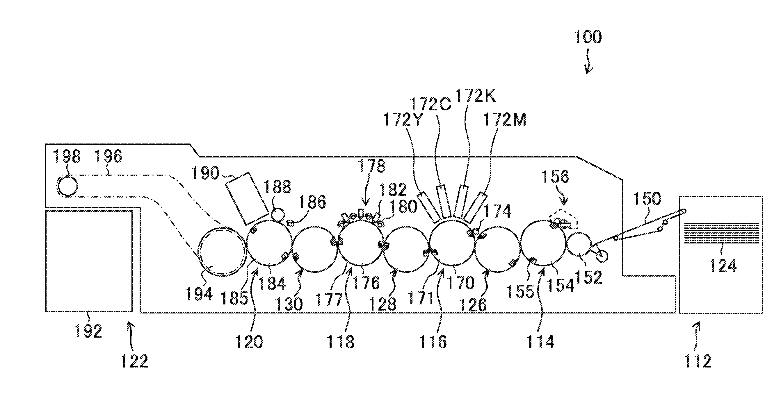
[0180]In the embodiment described above, a drum conveyance method is used, but the composition for performing relative scanning of the paper and head is not limited to this. For example, it is also possible to adopt a mode in which the paper is fixed to a flat plate-shaped stage and the stage is conveyed in the y direction. In this case, it is possible to employ a mode for driving the stage by providing a linear gear (rack) on the stage, for example, as a device for moving the stage, and rotating a gear wheel (pinion) which meshes with the rack. Furthermore, instead of a rack and pinion system of this kind, it is also possible to employ a composition which uses a ball screw and moves a stage in the axial direction of the ball screw by turning the ball screw. In this case, the period obtained when the pitch of the ball screw is projected onto the paper is handled as Pv.

modification example 2

[0181]In the embodiment described above, an example is given in which a recording medium is conveyed with respect to a stationary head, but in implementing the present invention, it is also possible to move a head with respect to a stationary recording medium (image formation receiving medium).

Recording Medium

[0182]In implementing the present invention, there are no particular restrictions on the material or shape, or other features, of the recording medium, and it is possible to employ various different media, irrespective of their material or shape, such as continuous paper, cut paper, seal paper, OHP sheets or other resin sheets, film, cloth, a printed substrate on which a wiring pattern, or the like, is formed, or a rubber sheet.

application examples

of the Present Invention

[0183]In the embodiment described above, application to an inkjet recording apparatus for graphic printing is described by way of example, but the scope of application of the present invention is not limited to this example. For example, the present invention can also be applied widely to inkjet systems which obtain various shapes or patterns using liquid function material, such as a wire printing apparatus which forms an image of a wire pattern for an electronic circuit, manufacturing apparatuses for various devices, a resist printing apparatus which uses resin liquid as a functional liquid for ejection, a color filter manufacturing apparatus, a fine structure forming apparatus for forming a fine structure using a material for material deposition, or the like.


PUM


Abstract

An inkjet image forming apparatus includes: a liquid ejection head having an ejection surface in which a plurality of nozzles are arranged two-dimensionally; a scanning device which conveys at least one of the liquid ejection head and an image formation receiving medium on which liquid ejected from the plurality of nozzles is deposited, to cause relative movement between the image formation receiving medium and the liquid ejection head in a first direction; a drive force generating device which generates drive force for driving the scanning device; and a meshing transmission mechanism which transmits the drive force generated by the drive force generating device to the scanning device by a meshing mechanism, wherein: when Pv represents a spatial period obtained by converting a pitch of meshing teeth of the meshing transmission mechanism to an amount of the relative movement in the first direction on the image formation receiving medium, and when OSy represents an offset distance in the first direction of a pair of nozzles which form dots that are mutually adjacent in a second direction perpendicular to the first direction on the image formation receiving medium, of the plurality of nozzles arranged two-dimensionally, then relationship of OSy≈k×Pv (where k is a natural number) is satisfied.

Description

BACKGROUND OF THE INVENTION[0001]1. Field of the Invention[0002]The present invention relates to an inkjet image forming apparatus, and more particularly to technology for improving image formation quality (image quality) in an inkjet image forming apparatus based on a single pass method which is equipped with an inkjet head having nozzles in a two-dimensional configuration.[0003]2. Description of the Related Art[0004]In the field of inkjet image formation, an inkjet image formation method (single pass method) is known in which, in order to achieve high image formation resolution and high productivity, head modules comprising a plurality of nozzles arranged in a two-dimensional configuration are formed, a long head (known as a “page-wide head” or “full line type head”) which covers an image formation area spanning the entire width of the paper is composed by aligning a plurality of sub-heads which are constituted by the head modules, in the paper width direction (hereinafter, called...

Claims


Application Information

Patent Timeline
Patent Type & Authority Applications(United States)
IPC IPC(8): B41J29/38
CPCB41J29/38B41J11/42
Inventor SUMI, KATSUTO
Owner FUJIFILM CORP
Why Eureka
Try Eureka