Inkjet image forming apparatus, method of designing same and method of improving image formation quality

a technology of inkjet image forming and nozzle arrangement, which is applied in the direction of printing, other printing apparatus, etc., can solve the problems of non-uniformity which degrades image quality, major problem of two-dimensional arrangement, image quality in two-dimensional nozzle arrangement, etc., to improve the effect of vibration non-uniformity, and improve the quality of image formation

Active Publication Date: 2011-09-29
FUJIFILM CORP
View PDF10 Cites 4 Cited by
  • Summary
  • Abstract
  • Description
  • Claims
  • Application Information

AI Technical Summary

Benefits of technology

[0051]In order to attain an object described above, another aspect of the present invention is directed to a method of improving image formation quality of an inkjet image forming apparatus including: a liquid ejection head having an ejection surface in which a plurality of nozzles are arranged two-dimensionally; a scanning device which conveys at least one of the liquid ejection head and an image formation receiving medium on which liquid ejected from the plurality of nozzles is deposited, to cause relative movement between the image formation receiving medium and the liquid ejection head in a first direction; and a member which vibrates at a fixed frequency that is independent of a speed of the relative movement caused by the scanning device in such a manner that relative vibration is caused between the image formation receiving medium and the plurality of nozzles, the method comprising the steps of: acquiring information indicating a relative scanning speed produced by the scanning device when forming an image on the image formation receiving medium by the relative movement and droplet ejection from the liquid ejection head; acquiring information indicating the fixed frequency of the member; acquiring information indicating an offset distance in the first direction of a pair of nozzles which form dots that are mutually adjacent in a second direction perpendicular to the first direction on the image formation receiving medium, of the plurality of nozzles arranged two-dimensionally; and changing at least one of the relative scanning speed produced by the scanning device and the fixed frequency of the member so as to satisfy relationship OSy≈k×vp / fv (where k is a natural number, vp represents the acquired relative scanning speed, fv represents the acquired fixed frequency, and OSy represents the acquired offset distance).
[0052]In general, there is little scope (degrees of freedom) for modification in the design of a nozzle arrangement, and in many cases it is easier to change the components of the drive force transmission system, change the components which constitute the supporting mechanism of the scanning system, or change the design. Furthermore, a liquid ejection head is expensive compared to the belt and other components of the drive force transmission system and the members such as the supporting frame of the scanning system, and the like. Consequently, according to this aspect of the invention, it is possible to improve the effects of vibration non-uniformity in a relatively simple fashion and at low cost, and it is possible to obtain an inkjet image forming apparatus which achieves good image formation quality. The sequence of a first step (step of acquiring information indicating the relative scanning speed), second step (step of acquiring information indicating the fixed frequency of the member) and third step (step of acquiring information indicating the offset distance) is not limited, provided that the respective information elements referred to in the fourth step (step of changing at least one of the relative scanning speed and the fixed frequency of the member) can be acquired.
[0053]According to the present invention, it is possible satisfactorily to reduce non-uniformity (vibration non-uniformity) which appears on an image formation receiving medium as a result of a two-dimensional nozzle arrangement and a vibration generating source which vibrates at a fixed frequency. Therefore, it is possible to achieve high image formation quality and high productivity.

Problems solved by technology

The causes of this relative displacement and vibration include, for instance, various mechanical shocks caused internally and externally to the image forming apparatus, displacement caused by the drive system for driving various moving parts including the paper conveyance system, and so on, and such factors manifest themselves as relative vibrations between the head and paper.
Of the relative vibration between the head and the paper, the vibration in the x direction in particular generates non-uniformity which causes problems of image quality in a two-dimensional nozzle arrangement.
However, in the case of a two-dimensional nozzle arrangement, as described hereinafter, a major problem which is characteristic of a two-dimensional arrangement occurs.
As a result of this, a “weighting (overlapping)” or “gap” appears between the dots (adjacent dots in the x direction) which are recorded by the y-offset adjacent nozzle pair, and the extent of this “weighting” or “gap” changes in the y direction, producing a non-uniformity which degrades the image quality.
In the description above, an example is given in which nozzles are arranged two-dimensionally in 2 rows (y direction) by N columns (x direction, where N is an integer and N≧2), but the present problem is not limited to this nozzle arrangement and a similar problem occurs in other two-dimensional nozzle arrangements (for example, an M row×N column two-dimensional nozzle arrangement, where M is an integer and M≧2).

Method used


Image

  • Inkjet image forming apparatus, method of designing same and method of improving image formation quality
  • Inkjet image forming apparatus, method of designing same and method of improving image formation quality
  • Inkjet image forming apparatus, method of designing same and method of improving image formation quality

Examples


concrete example 1

[0155]A plurality of candidates are prepared as the setting value for the paper conveyance speed, and the paper conveyance speed is set to a desired speed by means of the operator performing a selection operation using a prescribed user interface (operating unit). For example, at least a first conveyance speed vp1 and a second conveyance speed vp2 are prepared as candidates for the conveyance speed. The speed vp1 is set as the default (initial setting) and the conveyance speed is changed to the second conveyance speed vp2 if a problem of non-uniformity arises, on the basis of the results of test printing or actual image printing at the speed (vp1), or the like.

concrete example 2

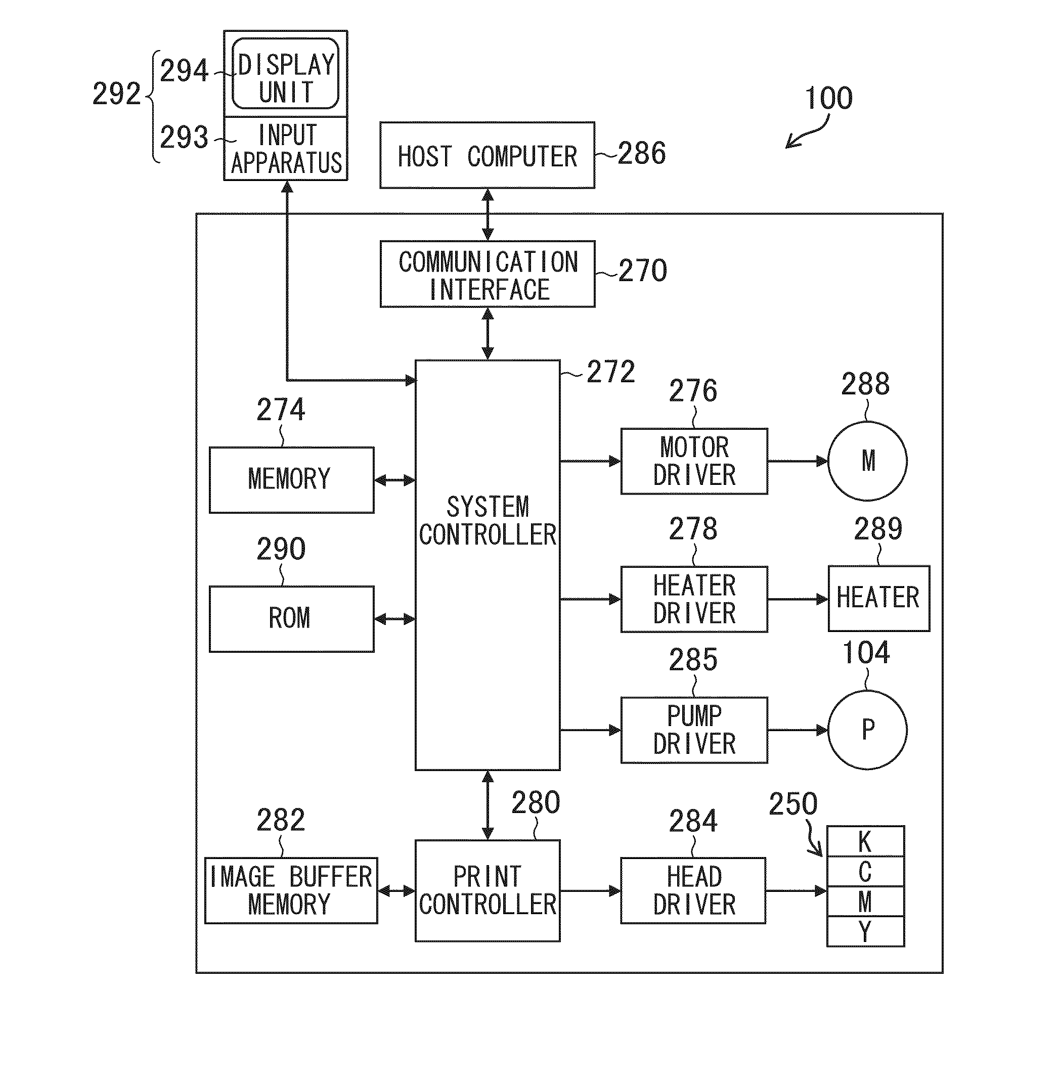
[0156]It is also possible to adopt a mode in which control is performed so as to automatically change the conveyance speed by means of a program, either instead of or in conjunction with manual operation by an operator as described in concrete example 1. For example, there is a mode in which the results of test printing are read in by an in-line sensor 190, the read image is analyzed, and the state of visibility of non-uniformity is judged automatically; if the occurrence of non-uniformity exceeding prescribed judgment criteria is confirmed, then processing is implemented to switch the conveyance speed setting to the second conveyance speed vp2. In this case also, it is possible to devise the program in such a manner that, before changing the conveyance speed setting, the operator is informed of the setting change and the setting change is only implemented after receiving input of an acknowledgment (confirmation OK) by the operator.

concrete example 3

[0157]As a further mode for changing the conveyance speed, it is also possible to indirectly select a conveyance speed setting which is designated for a particular image formation mode, by selecting the desired particular image formation mode from a plurality of image formation modes (print modes) having different conveyance speed settings.

[0158]For example, there is a high image quality mode for use when image output having very high definition is required and a normal image quality mode (low quality mode) for use when image output of lower image quality than this is tolerated, and the conveyance speed vp3 for image formation in the high quality mode and the conveyance speed vp4 for image formation in the normal quality mode are set to mutually different speeds. In particular, the conveyance speed vp relating to the high quality mode, namely vp3 (vp=vp3), is specified so as to satisfy Relationship 1′, Relationship 2′ or Relationship 3′.

[0159]It is also possible to adopt a compositi...


PUM


Abstract

An inkjet image forming apparatus includes: a liquid ejection head having an ejection surface in which a plurality of nozzles are arranged two-dimensionally; a scanning device which conveys at least one of the liquid ejection head and an image formation receiving medium on which liquid ejected from the plurality of nozzles is deposited, to cause relative movement between the image formation receiving medium and the liquid ejection head in a first direction; and a member which vibrates at a fixed frequency that is independent of a speed of the relative movement caused by the scanning device in such a manner that relative vibration is caused between the image formation receiving medium and the plurality of nozzles, wherein when vp represents a relative scanning speed produced by the scanning device in forming an image on the image formation receiving medium by the relative movement and droplet ejection from the liquid ejection head, fv represents the fixed frequency, and OSy represents an offset distance in the first direction of a pair of nozzles which form dots that are mutually adjacent in a second direction perpendicular to the first direction on the image formation receiving medium, of the plurality of nozzles arranged two-dimensionally, then relationship of OSy≈k×vp/fv (where k is a natural number) is satisfied.

Description

BACKGROUND OF THE INVENTION[0001]1. Field of the Invention[0002]The present invention relates to an inkjet image forming apparatus, and more particularly to technology for improving image formation quality (image quality) in an inkjet image forming apparatus based on a single pass method which is equipped with an inkjet head having nozzles in a two-dimensional configuration.[0003]2. Description of the Related Art[0004]In the field of inkjet image formation, an inkjet image formation method (single pass method) is known in which, in order to achieve high image formation resolution and high productivity, head modules comprising a plurality of nozzles arranged in a two-dimensional configuration are formed, a long head (known as a “page-wide head” or “full line type head”) which covers an image formation area spanning the entire width of the paper is composed by aligning a plurality of sub-heads which are constituted by the head modules, in the paper width direction (hereinafter, called...

Claims


Application Information

Patent Timeline
Patent Type & Authority Applications(United States)
IPC IPC(8): B41J29/38B41J23/02B41J29/393
CPCB41J2/2146B41J23/02B41J29/38
Inventor SUMI, KATSUTO
Owner FUJIFILM CORP
Why Eureka
Try Eureka