
Shallow groove isolation construction, forming method and grinding method

A technology of isolation structure and grinding method, which is applied in the manufacture of electrical components, electrical solid devices, semiconductor/solid devices, etc., can solve problems such as edge depressions, achieve low turntable speed, reduce damage, and improve uniformity and consistency.

Inactive Publication Date: 2009-06-17
SEMICON MFG INT (SHANGHAI) CORP
View PDF1 Cites 4 Cited by
  • Summary
  • Abstract
  • Description
  • Claims
  • Application Information

AI Technical Summary

Problems solved by technology

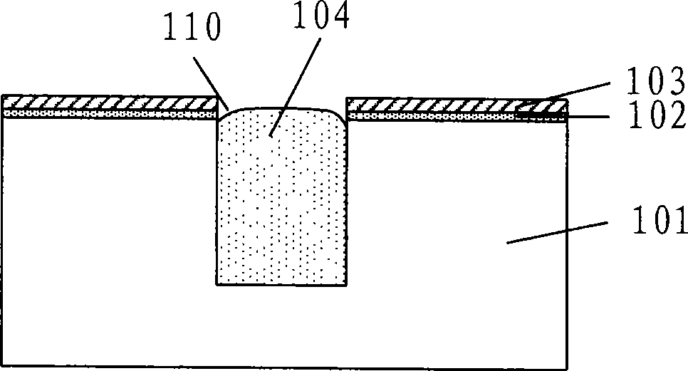
[0009] The invention provides a shallow trench isolation structure, a forming method and a grinding method, so as to improve the phenomenon that the existing shallow trench isolation structure is prone to edge depressions after grinding

Method used


Image

  • Shallow groove isolation construction, forming method and grinding method
  • Shallow groove isolation construction, forming method and grinding method
  • Shallow groove isolation construction, forming method and grinding method

Examples


no. 1 example

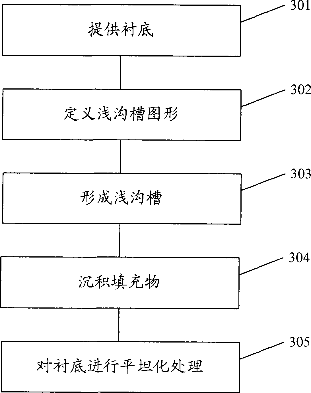
[0078] This embodiment introduces a method for forming a shallow trench isolation structure, image 3 is a flow chart of the method for forming the shallow trench isolation structure according to the first embodiment of the present invention, Figure 4 to Figure 8 In order to illustrate the device cross-sectional schematic diagram of the method for forming the shallow trench isolation structure in the first embodiment of the present invention, the following is combined with Figure 3 to Figure 8 The first embodiment of the present invention will be described in detail.

[0079] The method for forming the shallow trench isolation structure of this embodiment includes the steps of:

[0080] Step 301: providing a substrate on which a stop layer has been formed.

[0081] Figure 4 is a schematic cross-sectional view of the substrate in the first embodiment of the present invention, as Figure 4 As shown, the substrate provided in this embodiment is a silicon substrate 401 on w...

no. 2 example

[0117] This embodiment introduces a polishing method, which improves the formation quality of the shallow trench isolation structure after polishing by adjusting the polishing end point and process conditions of the shallow trench isolation structure.

[0118] Figure 11 A schematic diagram of the chemical mechanical grinding device used in the grinding method of the second embodiment of the present invention, such as Figure 11 As shown, the device includes: a housing 1101, a turntable (platen) 1102 with a polishing pad (polish pad) attached to the surface, polishing heads 1103a, 1103b and a polishing liquid supply pipe (tube) 1104 for transporting a polishing liquid (slurry) 1105 .

[0119] When grinding, the substrate to be polished is first attached to the grinding head 1103, and the substrate is pressed against the grinding pad by applying downward pressure on the grinding head 1103; then, the turntable 1102 with the grinding pad attached to the surface is driven by the ...


PUM


Abstract

The invention discloses a forming method of a shallow trench isolation structure, which comprises steps of providing a substrate with a shaped stop layer, defining a shallow trench pattern on the substrate, forming a shallow trench in the substrate with the shaped stop layer, depositing filling materials in the shallow trench and on the stop layer, flattening the substrate after the filling materials are deposited, wherein dishing of the filling materials in the shallow trench can be prevented by controlling the attitude difference between the filling materials in the shallow trench and the stop layer in the flattening process. The invention further provides a relative shallow trench isolation structure and a polishing method thereof. After utilizing the polishing method, the shallow trench isolation structure and the forming method thereof, flattening of the filling materials in the shallow trench can be maintained, and forming quality of the shallow trench isolation structure is increased.

Description

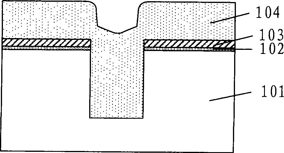
technical field [0001] The invention relates to the technical field of semiconductor manufacturing, in particular to a shallow trench isolation structure, a forming method and a grinding method. Background technique [0002] With the continuous reduction of the feature size of semiconductor devices, the isolation area between devices is also reduced accordingly, and the requirements for device isolation are getting higher and higher. It will form a "bird's beak" (BIRD'S BEAK) region at the boundary of the active region, which will expand the separation region and other problems, which have been gradually replaced by shallow trench isolation technology (STI, Shallow Trench Isolation). Using STI technology to prepare isolation regions to achieve isolation between devices has the advantage of making the most effective use of the line width of the active region and improving integration. [0003] figure 1 It is a schematic cross-sectional view of the device after filling the S...

Claims


Application Information

Patent Timeline
Patent Type & Authority Applications(China)
IPC IPC(8): H01L21/762H01L27/02H01L21/3105
Inventor 李健
Owner SEMICON MFG INT (SHANGHAI) CORP
Learn More