
LED illuminating device with prism sheet

Inactive Publication Date: 2012-03-29
HON HAI PRECISION IND CO LTD
View PDF13 Cites 1 Cited by
  • Summary
  • Abstract
  • Description
  • Claims
  • Application Information

AI Technical Summary

Benefits of technology

[0005]Therefore, what is needed is an LED illuminating device that can reduce the number of LEDs used, yet still achieve a desirable level of the luminance.

Problems solved by technology

Despite its many advantages, the luminous intensity of an LED is limited.
This disadvantage requires quite a number of LEDs for a large lighting system to reach a desired luminance.

Method used


Image

  • LED illuminating device with prism sheet
  • LED illuminating device with prism sheet
  • LED illuminating device with prism sheet

Examples


Embodiment Construction

[0013]Embodiments of the present disclosure are now described in detail, with reference to the accompanying drawings.

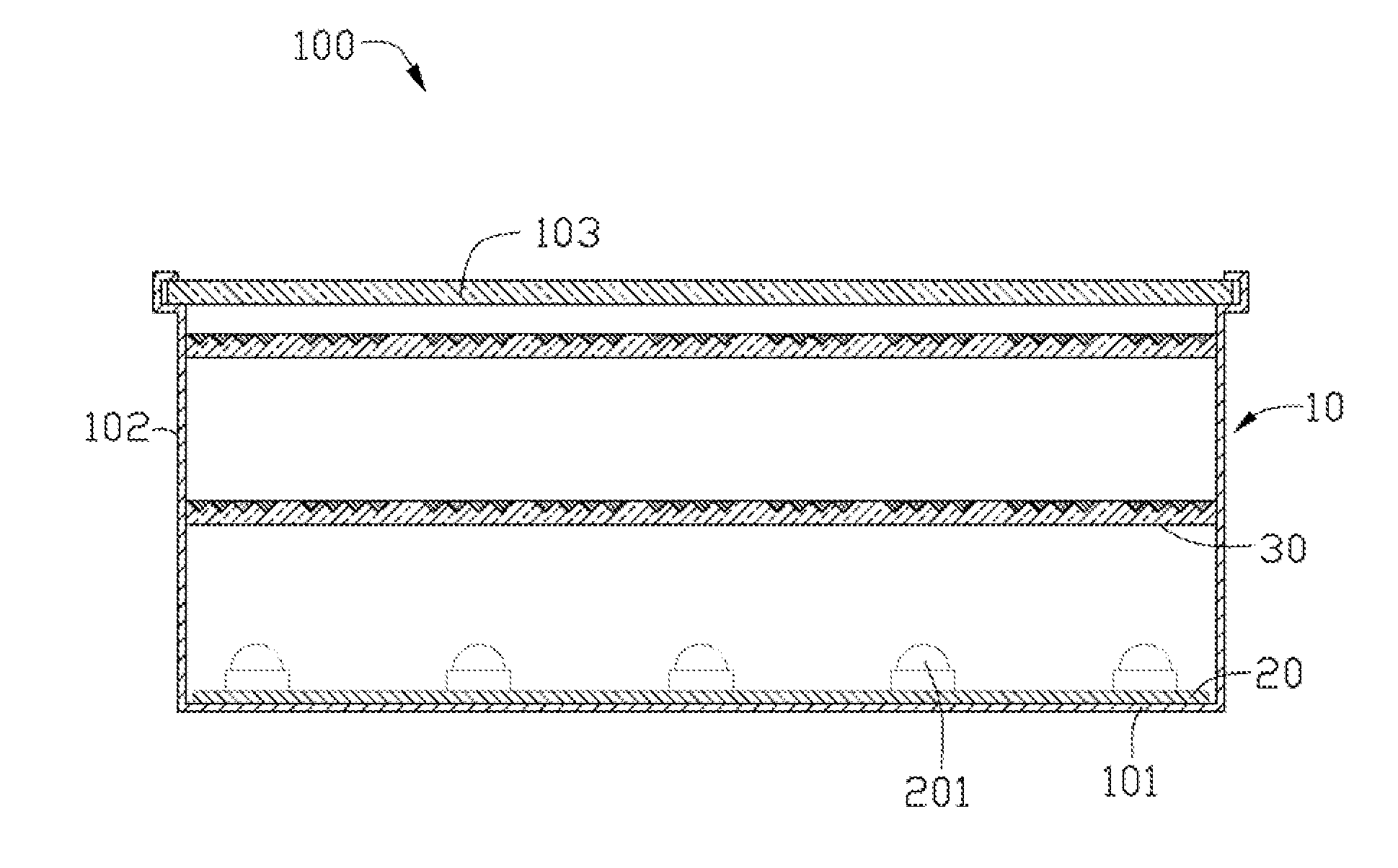
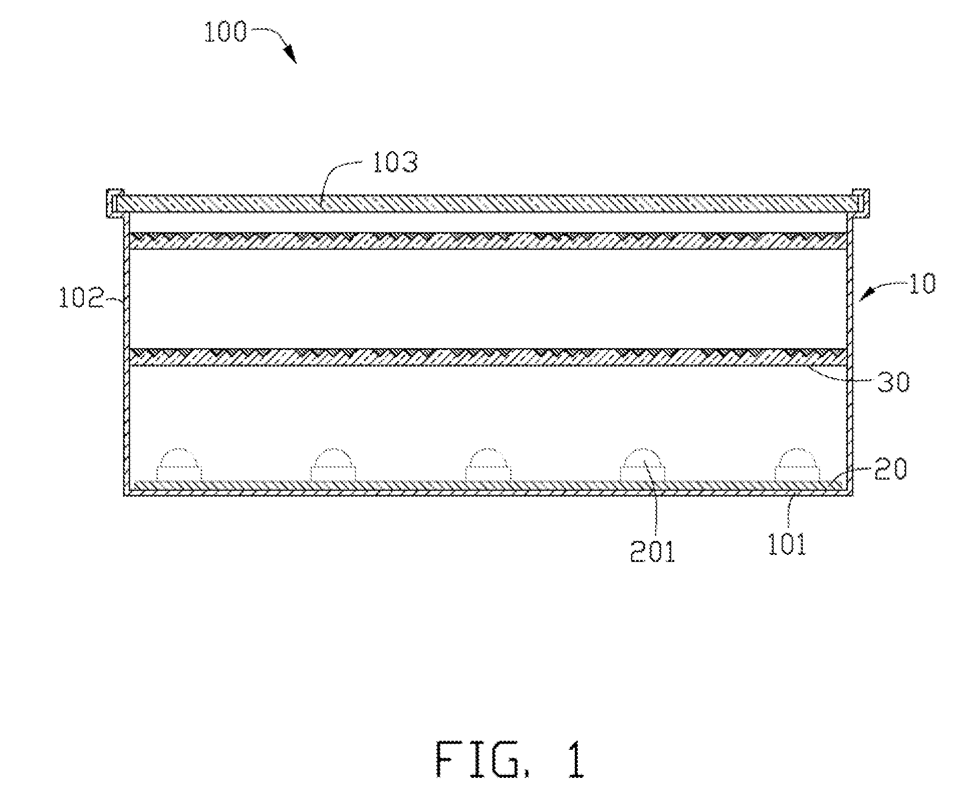
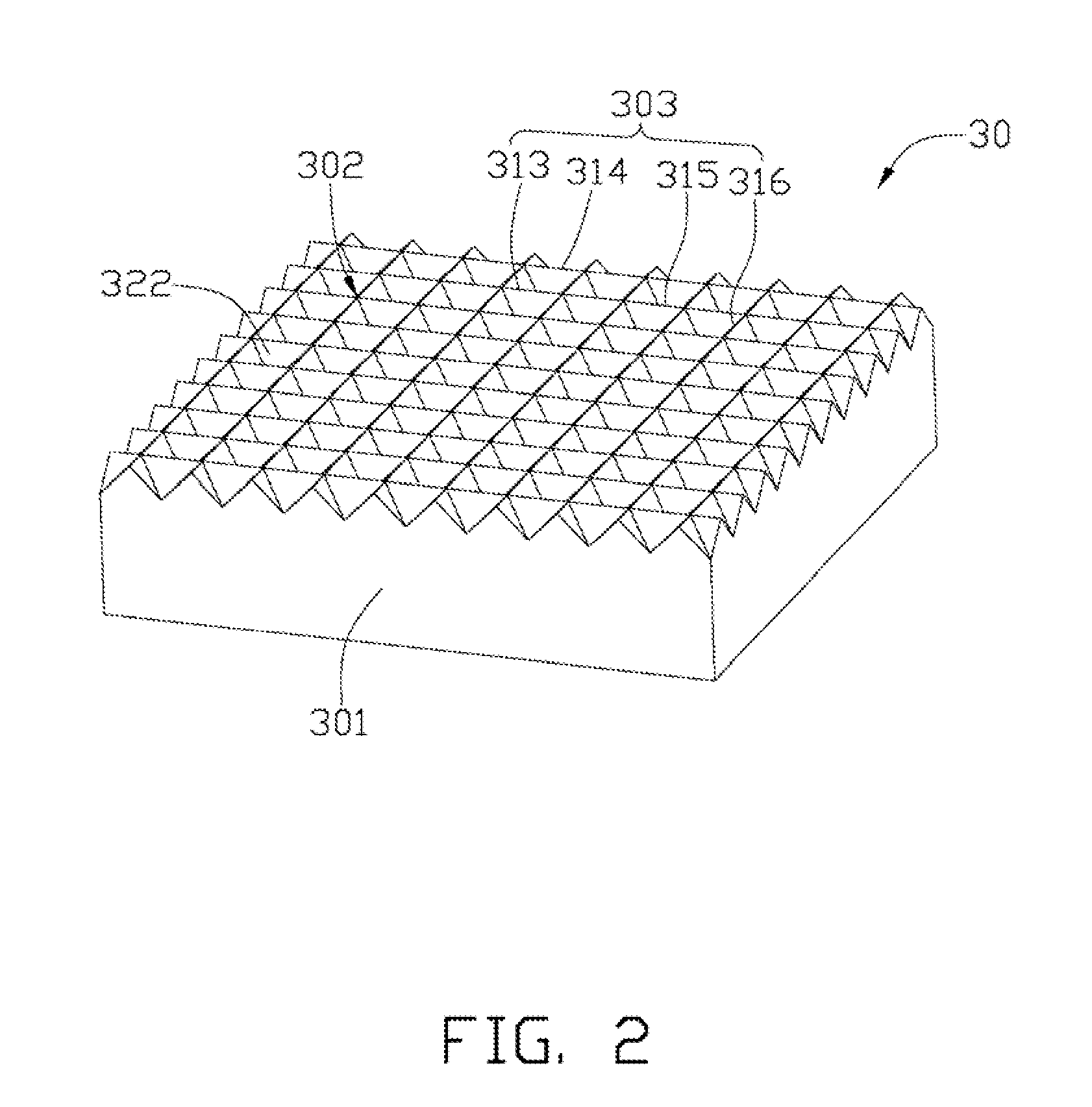
[0014]Referring to FIG. 1, an LED illuminating device 100 according to an embodiment is disclosed. The LED illuminating device 100 includes a housing 10, a circuit board 20, and a prism sheet 30. At least one LED unit 201 is arranged on the circuit board 20 and the color emitted by each LED unit 201 is the same as the other LED unit 201. The housing 10 includes a base plate 101, a sidewall 102 surrounding the base plate 101, and a cover 103. The circuit board 20 is fixed on the base plate 101, and the prism sheet 30 is arranged above the circuit board 20 and substantially parallel to the circuit board 20. The protection cover 103 is fixed on the sidewall 102 and placed above the prism sheet 30 for protecting the prism sheet 30 and the circuit board 20 from being contaminated and damaged. In the embodiment, the protection cover 103 is made of transparent glass or trans...


PUM


Abstract

An LED illuminating device contains a housing with a base plate, a prism sheet and a circuit board. The prism sheet is mounted in the housing and includes a number of V-shaped micro-grooves along at least two directions intersecting with each other. The circuit board arranged multiple of LED illuminating arrays is fixed on the base plate. Each LED illuminating array is made of two LED units spaced apart a third preset distance. At least four virtual light sources are formed by the reflection of prism sheet to the circuit board after the light emitted by a particular LED unit on the circuit board. The rows and the columns of the matrix are respectively spaced apart a first preset distance and a second preset distance.

Description

BACKGROUND[0001]1. Technical Field[0002]The present disclosure relates to light emitting diode (LED) illuminating devices, especially to an LED illuminating device with prism sheet.[0003]2. Description of Related Art[0004]In comparison to other kinds of illuminating devices, LED illuminating devices have advantages such as high luminous efficiency, low power consumption, and long service life. Despite its many advantages, the luminous intensity of an LED is limited. This disadvantage requires quite a number of LEDs for a large lighting system to reach a desired luminance.[0005]Therefore, what is needed is an LED illuminating device that can reduce the number of LEDs used, yet still achieve a desirable level of the luminance.BRIEF DESCRIPTION OF THE DRAWINGS[0006]Many aspects of the embodiments can be better understood with reference to the following drawings. The components in the drawings are not necessarily drawn to scale. The emphasis is instead being placed upon clearly illustra...

Claims


Application Information

Patent Timeline
IPC IPC(8): F21V5/02
CPCF21V5/02F21Y2113/002F21Y2105/001F21Y2101/02F21Y2105/10F21Y2113/10F21Y2115/10
Inventor CHANG, SHAO-HAN
Owner HON HAI PRECISION IND CO LTD
Learn More