Eureka AIR delivers breakthrough ideas for toughest innovation challenges, trusted by R&D personnel around the world.

Object detection device

Inactive Publication Date: 2012-03-29
CHUBU UNIV EDUCATIONAL F
View PDF23 Cites 86 Cited by
  • Summary
  • Abstract
  • Description
  • Claims
  • Application Information

AI Technical Summary

Benefits of technology

[0007]In light of the foregoing, it is an object of the present invention to improve the accuracy of object detection by an object detection device that detects an object based on an input image. An additional object of the present invention is to increase the speed of the detection of the object by the object detection device.Solution to Problem
[0009]Using the depth histogram features that use the depth image to identify the depth relationships between local regions in this manner makes it possible to identify the boundary between the target of detection and the background, even in the case of a highly complex background, thus making it possible to improve the accuracy of the object detection.
[0011]Using the depth information from the depth image thus makes it possible to identify the occlusion region easily, so the object detection can be performed while taking the occlusion region into consideration. That makes it possible to improve the accuracy of the object detection even more.
[0013]Using the depth image that includes the depth information makes it possible to specify the size of the target of detection according to the depth in the three-dimensional space. Therefore, in a case where the raster scanning is performed in the three-dimensional space, the depth images that do not match the size of the object can be excluded, so the speed at which the object is detected can be increased over what it is in a case where the raster scanning is performed in a two-dimensional space.
[0014]Furthermore, the invention according to a fourth aspect is characterized in that the depth image acquisition means is a time-of-flight (TOF) camera. The TOF camera does not require that a correspondence between images be calculated, as is necessary with a stereo camera, so it can increase the speed at which the object is detected.

Problems solved by technology

In order for a technology that monitors people in this manner to be implemented, it is necessary to know where the people are within the space, and the implementation of advanced human detection has become an issue.

Method used


Image

  • Object detection device
  • Object detection device
  • Object detection device

Examples


Embodiment Construction

[0025]Hereinafter, an embodiment that uses an object detection device according to the present invention will be explained. The object detection device according to the present embodiment analyzes a depth image that includes depth information for each pixel and detects an object that is contained in the depth image. In the present embodiment, the object detection device will be used as a human detection device for detecting a human.

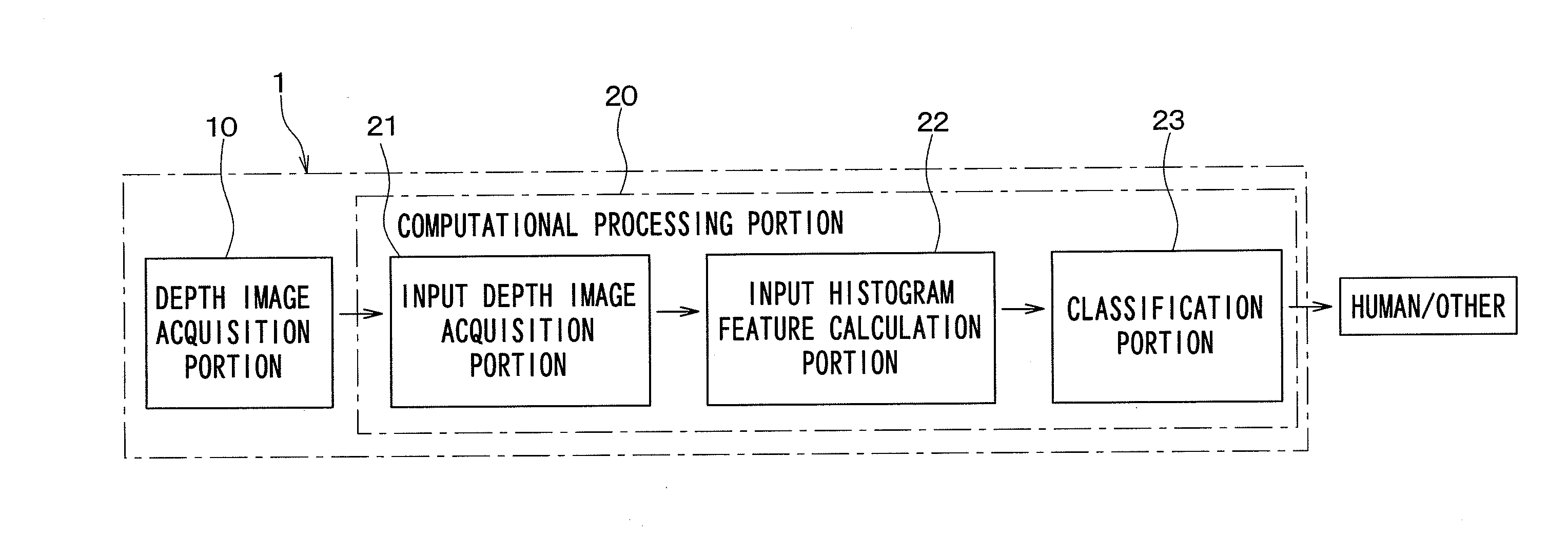
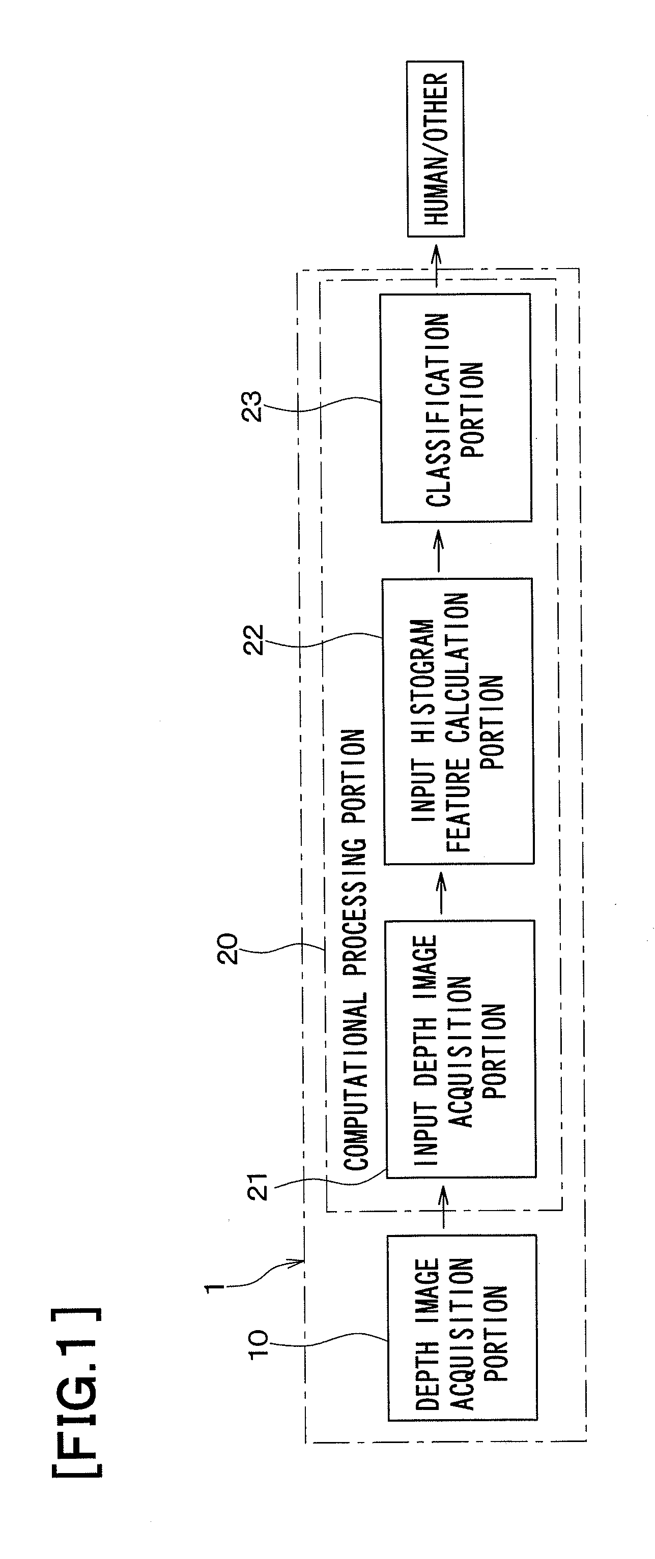
[0026]FIG. 1 is a conceptual diagram of a human detection device 1 according to the present embodiment. As shown in FIG. 1, the object detection device according to the present embodiment is provided with a depth image acquisition portion 10 and a computational processing portion 20. The computational processing portion 20 is configured from an input depth image acquisition portion 21, a depth histogram feature calculation portion 22, and a classification portion 23.

[0027]The depth image acquisition portion 10 is a depth measurement means such as a camera...


PUM


Abstract

A depth histogram is created for each of a plurality of local regions of the depth image by grouping, according to specified depths, the depth information for the individual pixels that are contained in the local regions. A degree of similarity between two of the depth histograms for two of the local regions at different positions in the depth image is calculated as a feature. A depth image for training that has a high degree of certainty is defined as a positive example, a depth image for training that has a low degree of certainty is defined as a negative example, a classifier that is suitable for classifying the positive example and the negative example is constructed, and an object that is a target of detection is detected in the depth image, using the classifier and based on the feature.

Description

CROSS REFERENCE TO RELATED APPLICATIONS[0001]This application is a U.S. national stage application of PCT / JP2010 / 059326 filed on Jun. 2, 2010, and claims priority to, and incorporates by reference, Japanese patent application No. 2009-133698 filed on Jun. 3, 2009.TECHNICAL FIELD[0002]The present invention relates to an object detection device that detects an object based on an input image.BACKGROUND ART[0003]In recent years, the implementation of a technology that will comprehend the intentions and assist the movements of people within spaces such as offices, homes, and public facilities has been anticipated. In order for a technology that monitors people in this manner to be implemented, it is necessary to know where the people are within the space, and the implementation of advanced human detection has become an issue.[0004]Much research has been done on human detection, and various types of methods have been proposed. Human detection methods that use known visible-light cameras i...

Claims


Application Information

Patent Timeline
IPC IPC(8): G06K9/00G01S17/894G06V10/50
CPCG06T7/004G06T2207/10028G06T2207/20021G06K9/4642G01S7/4802G06K9/00201G06K9/00369G01S17/89G06T7/70G01S17/894G06V20/64G06V40/103G06V10/50
Inventor FUJIYOSHI, HIRONOBU
Owner CHUBU UNIV EDUCATIONAL F
Why Eureka
Eureka Blog
Learn More