Apparatus for soil compaction

a technology of soil compaction and apparatus, applied in soil preservation, roads, roads, etc., can solve the problems of serious damage, buckling of the machine, and the full weight of the vibration tamper foot, so as to prevent the effect of buckling

Inactive Publication Date: 2012-03-29
BOMAG
View PDF11 Cites 4 Cited by
  • Summary
  • Abstract
  • Description
  • Claims
  • Application Information

AI Technical Summary

Benefits of technology

[0036]It is not only possible in such a case to arrange the stop element as a stop disk which is arranged in a complementary manner in relation to the inside geometry of the outside guide and which comprises a lead-through opening for the drive train especially in a centric manner. As a result, the stop element is guided through the inside wall of the outside guide and/or through the drive train extend...

Problems solved by technology

It may occur, however, that the vibration tamper will fall onto the tamper foot with its full weight during unloading from a truck, for e...

Method used


Image

  • Apparatus for soil compaction
  • Apparatus for soil compaction
  • Apparatus for soil compaction

Examples


Embodiment Construction

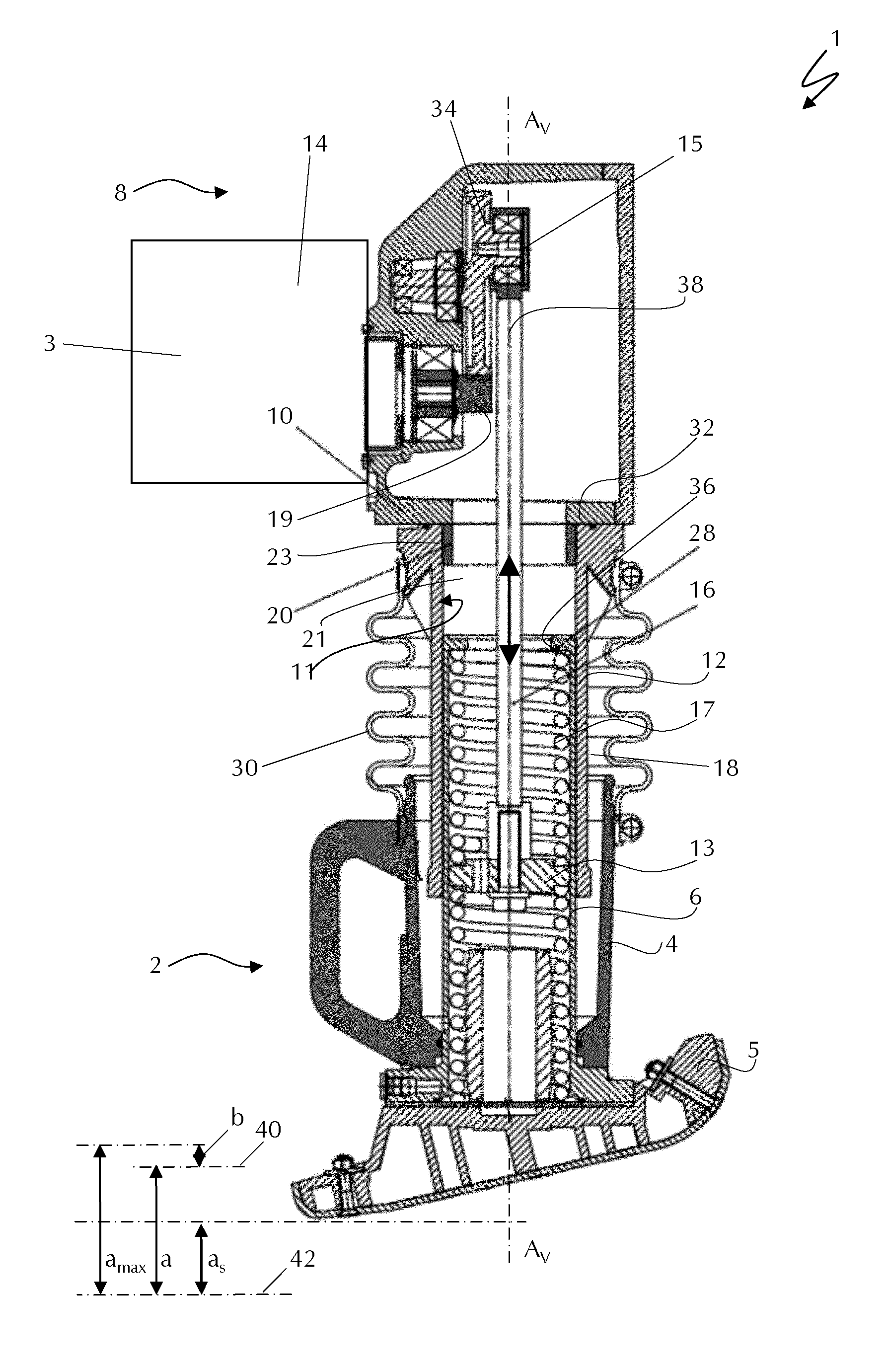
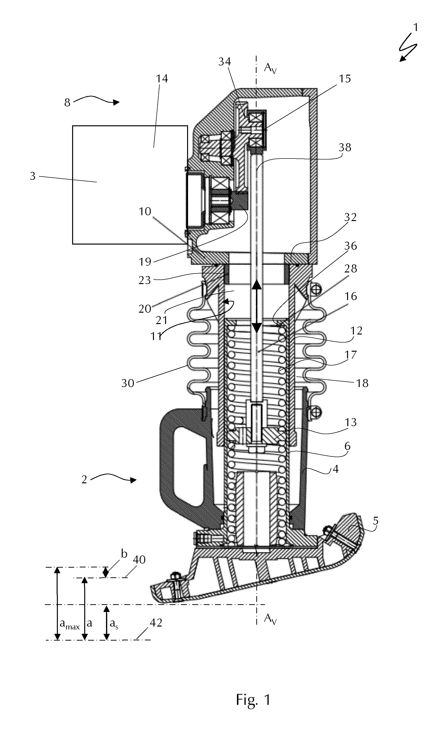
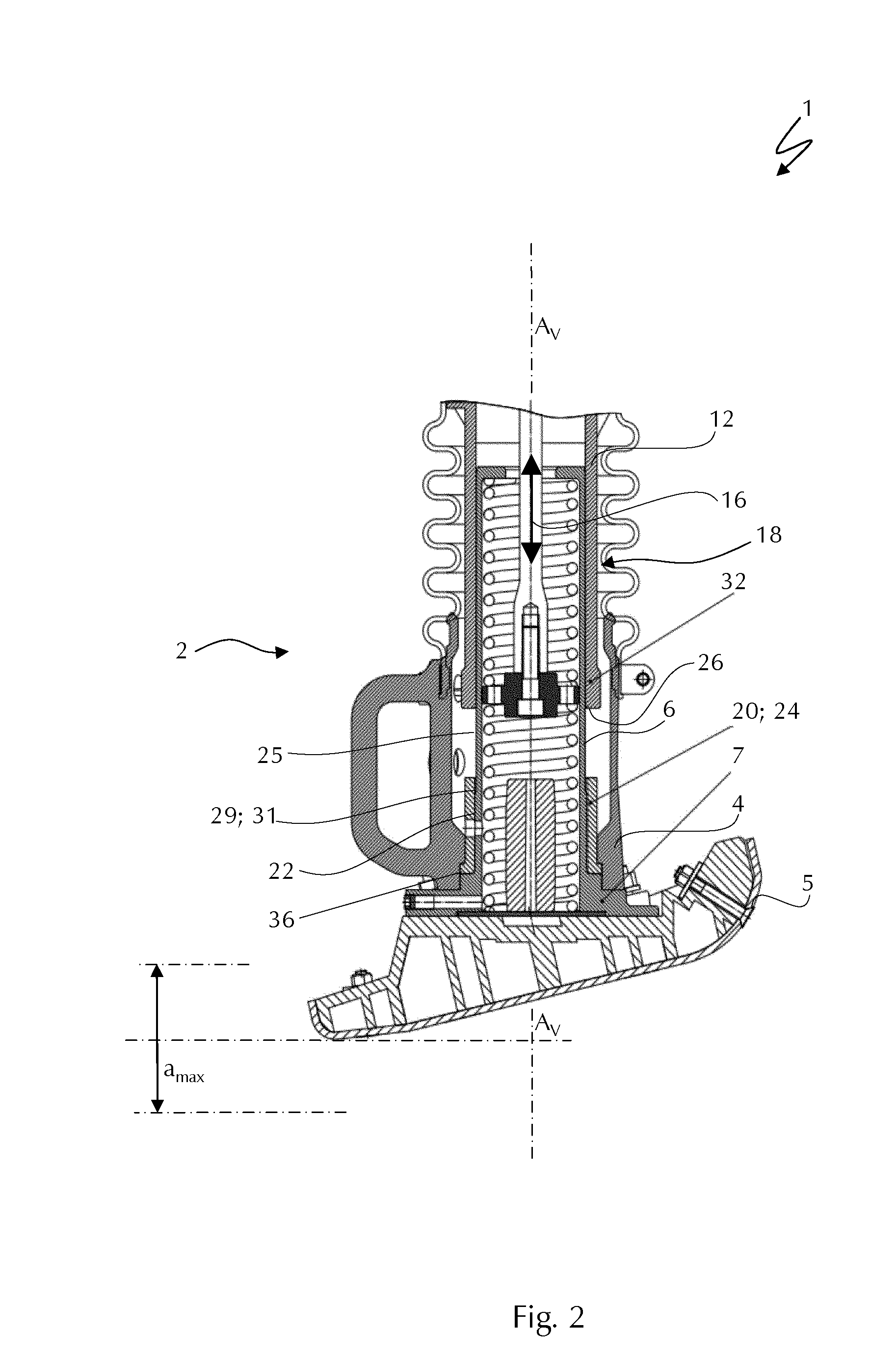
[0041]FIG. 1 shows a longitudinal sectional view through an embodiment of the apparatus for soil compaction in accordance with the present invention and especially a vibration tamper 1. The vibration tamper 1 comprises a superstructure 8 and a substructure 2 which are movable relative to one another. This movement is guided by way of an upper guide cylinder 12 which is in axial sliding connection with a bottom guide cylinder 6 coaxially to the compaction axis Av. The upper guide cylinder 12 is arranged in a stationary manner on a housing 10 of the superstructure 8, whereas the bottom guide cylinder 6 is connected in a stationary manner with a tamper plate 5 and forms a tamper foot 4. The two guide cylinders 6, 12 are movable relative to one another in such a way that a tamping movement for soil compaction can be performed within the scope of a compaction amplitude a along the compaction axis AV.

[0042]In this embodiment, the upper guide cylinder 12 forms an outside guide into which o...


PUM


Abstract

An apparatus for soil compaction, such as a vibration tamper, comprises a substructure having a tamper foot and a bottom guide cylinder arranged thereon, and a superstructure having a housing, an upper guide cylinder arranged thereon and at least one drive unit which is in operative connection via a drive train with the tamper foot in the substructure in such a way that it can be moved relative to the superstructure along at least one compaction axis (Av) with at least one compaction amplitude (a), with at least one stop element being arranged between the superstructure and the substructure, which stop element will stop the movement of the substructure relative to the superstructure upon exceeding a maximum compaction amplitude (amax).

Description

CROSS-REFERENCE TO RELATED APPLICATIONS[0001]The present application claims priority under 35 U.S.C. §119 of German Patent Application No. 10 2010 046 820.7, filed Sep. 28, 2010, the disclosure of which is hereby incorporated herein by reference in its entirety.FIELD OF THE INVENTION[0002]The present invention relates to an apparatus for soil compaction and especially a vibration tamper with a substructure, comprising a tamper foot and a bottom guide cylinder arranged thereon, and a superstructure, comprising a housing, an upper guide cylinder arranged thereon and at least one drive unit which is in operative connection via a drive train with the tamper foot in the substructure in such a way that it can be moved relative to the superstructure along at least one compaction axis with at least one compaction amplitude, with the upper guide cylinder and the bottom guide cylinder being movable relative to one another in the direction of the compaction axis by forming at least one axial g...

Claims


Application Information

Patent Timeline
IPC IPC(8): E01C19/34
CPCE01C19/35E01C19/38E01C19/34E02D3/046E02D3/068
Inventor BONNEMANN, DIRKSTEEG, THOMAS
Owner BOMAG
Why Eureka
Try Eureka