

Method of and device for determining a mass condition of a rotor of a wind turbine, and method of operating a wind turbine
a technology of a rotor and a mass condition, which is applied in the field of wind turbines, can solve the problems of high cost and complexity of above-mentioned techniques for determining the mass condition of the rotor, and adversely affect the output power of the wind turbine, and achieve the effect of accurate, easy and reliable determination
- Summary
- Abstract
- Description
- Claims
- Application Information
AI Technical Summary
Benefits of technology
Problems solved by technology
Method used
Image

Examples
Embodiment Construction
[0072]The illustration in the drawing is schematic. It is noted that in different figures, similar or identical elements are provided with the same reference signs or with reference signs, which are different from the corresponding reference signs only within the first digit.
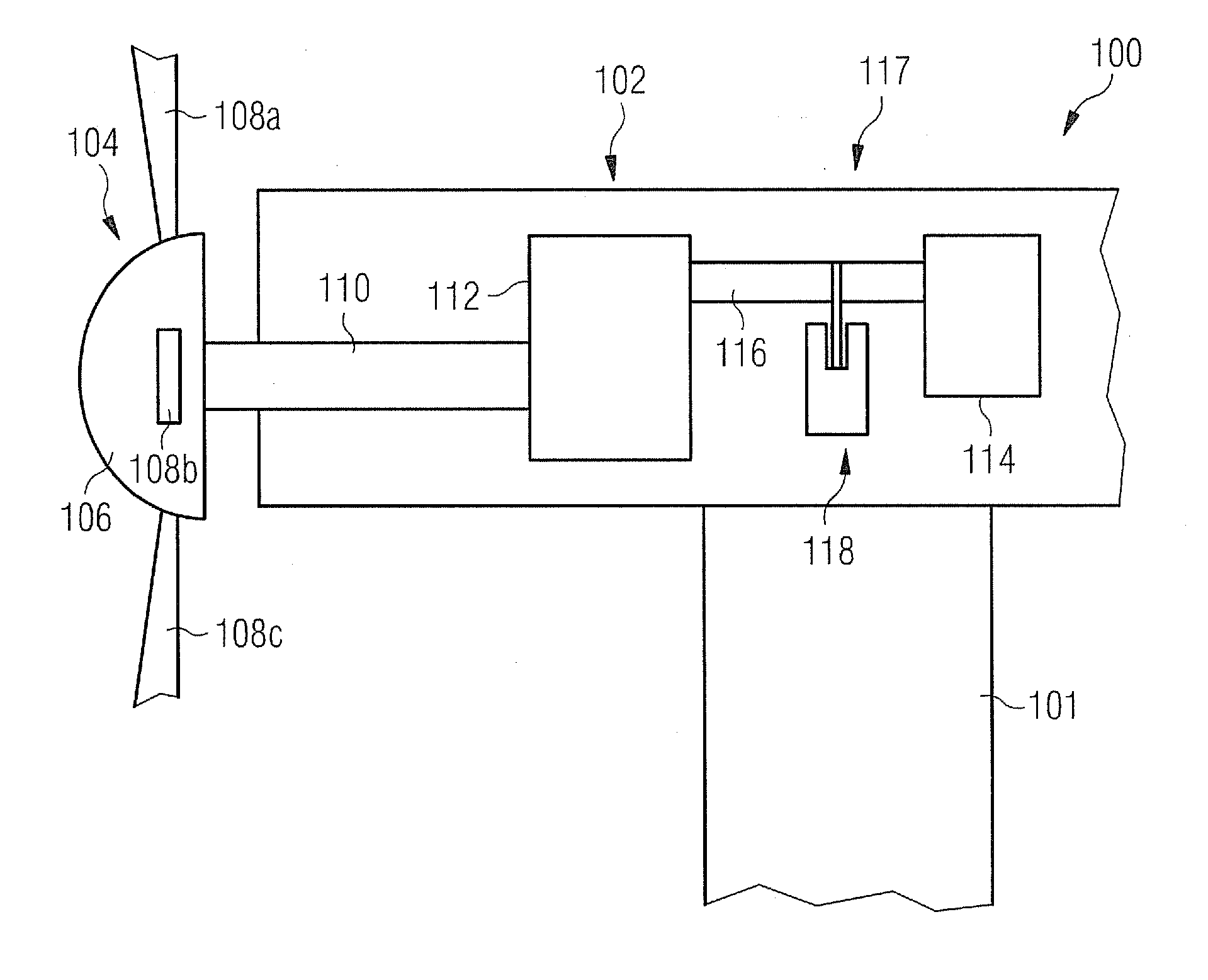
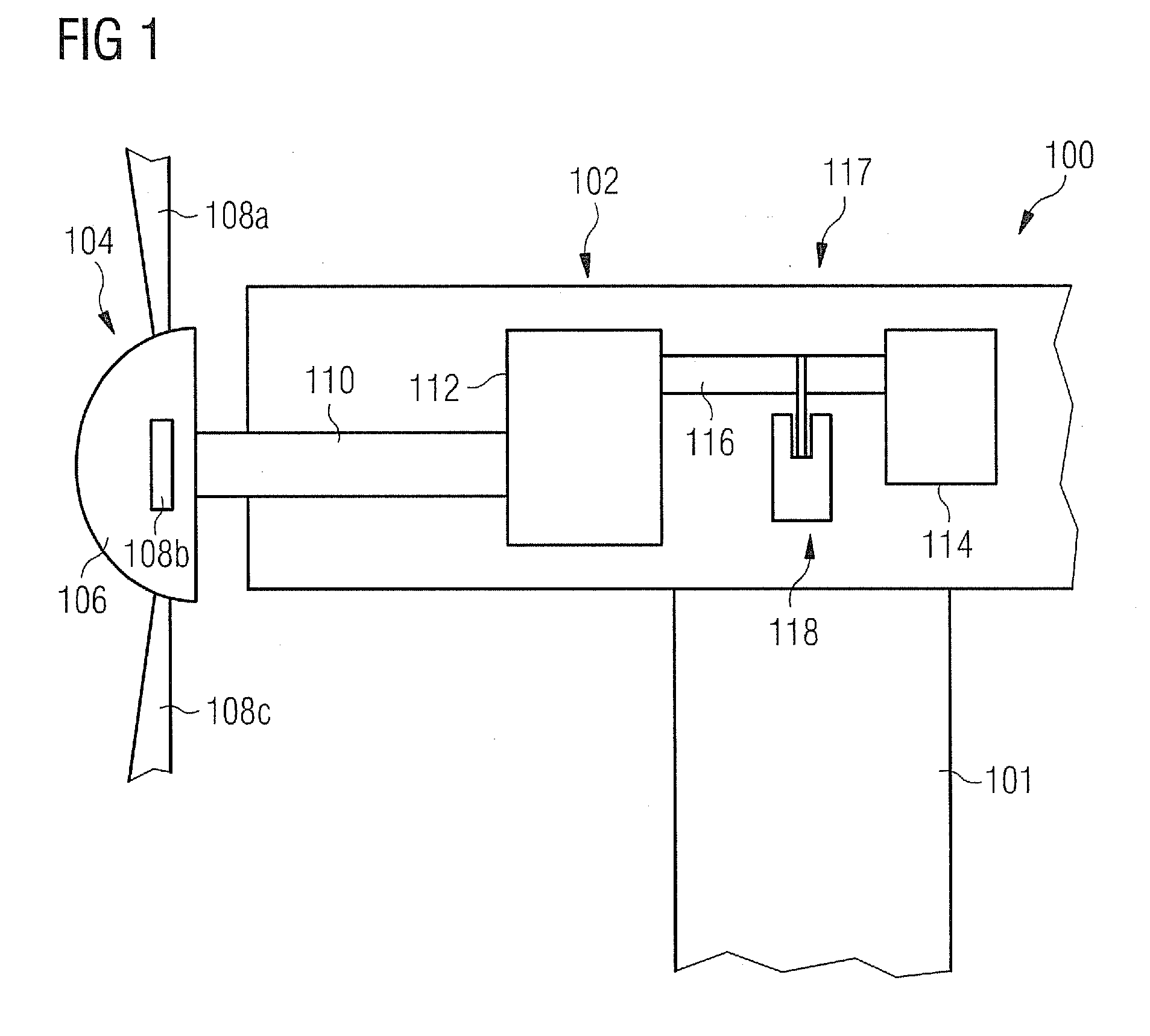
[0073]Referring to FIG. 1, a partial perspective view a wind turbine 100 is illustrated. The wind turbine 100 comprises a tower 101, a nacelle 102, and a rotor 104.
[0074]The rotor 104 is rotatably movable with respect to the nacelle 102 and comprises a hub 106 and blades 108a-c which are rotatably fixed at the hub 106. The rotor 104 is attached to a rotor shaft 110 which extends along a longitudinal extension of the nacelle 102. The rotor shaft 110 defines a rotational axis around which the rotor 104 is rotatable.
[0075]The rotor shaft 110 is connected to a gearbox 112 which is connected to a generator 114 via a generator shaft 116. The rotor shaft 110, the gearbox 112, and the generator shaft 116 represent a dri...
PUM
 Abstract
Description
Claims
Application Information