Pedicle screws and dynamic adaptors

a technology of dynamic adaptors and pedicle screws, applied in the field of medical devices, can solve the problems of difficult assembly and manipulation of components, high post-surgical failure rate and many drawbacks of conventional pedicle screws

Inactive Publication Date: 2012-03-29
SPINOFIX
View PDF8 Cites 85 Cited by
  • Summary
  • Abstract
  • Description
  • Claims
  • Application Information

AI Technical Summary

Benefits of technology

[0013]In yet another embodiment, the present invention may include a dynamic adaptor, which may be used in conjunction with first and second stabilizing rods and for stabilizing one or more spinal bone segments. The dynamic adaptor may be configured to allow a relative movement between the first and second stabilizing rods. The dynamic adaptor may have a cylindrical sleeve having first and second ports, and a side wall extension formed between the first and second ports, the first and second ports configured to receive a segment of the second stabilizing rod, the side wall extension configured to be coupled to the first stabilizing rod, the cylindrical sleeve allowing the segment of the stabilizing rod to have a range of radial movement therein, the range of radial movement defining the relative movement between the first and second stabilizing rods, and a stopper configured to be coupled to the segment of the second stabilizing rod, the stopper engaging the second port of the cylindrical sleeve and configured to prevent the segment of the second stabilizing rod from leaving the first port of the cylindrical sleeve.

Problems solved by technology

Conventional pedicle screws may suffer from several drawbacks.
For example, conventional pedicle screws may include components that are difficult to assembly and manipulate.
In another example, conventional pedicle screws may have a high post surgical failure rate due to poor durability and low resistance to mechanical stresses.
Moreover, conventional stabilizing rods may generally be made of strong and rigid materials, such that the tasks of securing and / or anchoring a conventional stabilizing rod to several non-linear anchoring points may be prohibitively difficult and time consuming.

Method used


Image

  • Pedicle screws and dynamic adaptors
  • Pedicle screws and dynamic adaptors
  • Pedicle screws and dynamic adaptors

Examples


Embodiment Construction

[0042]Apparatus, systems and methods that implement the embodiment of the various features of the present invention will now be described with reference to the drawings. The drawings and the associated descriptions are provided to illustrate some embodiments of the present invention and not to limit the scope of the present invention. Throughout the drawings, reference numbers are re-used to indicate correspondence between reference elements. In addition, the first digit of each reference number indicates the figure in which the element first appears.

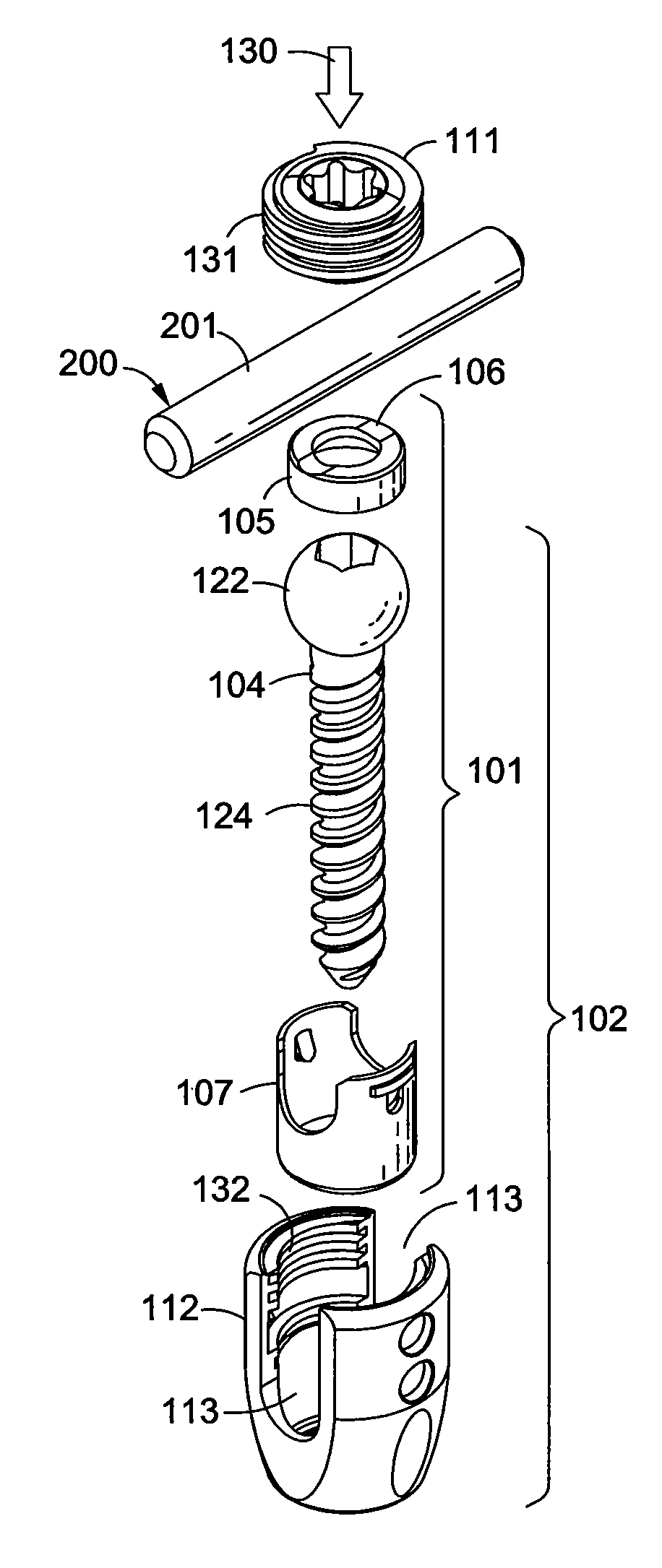
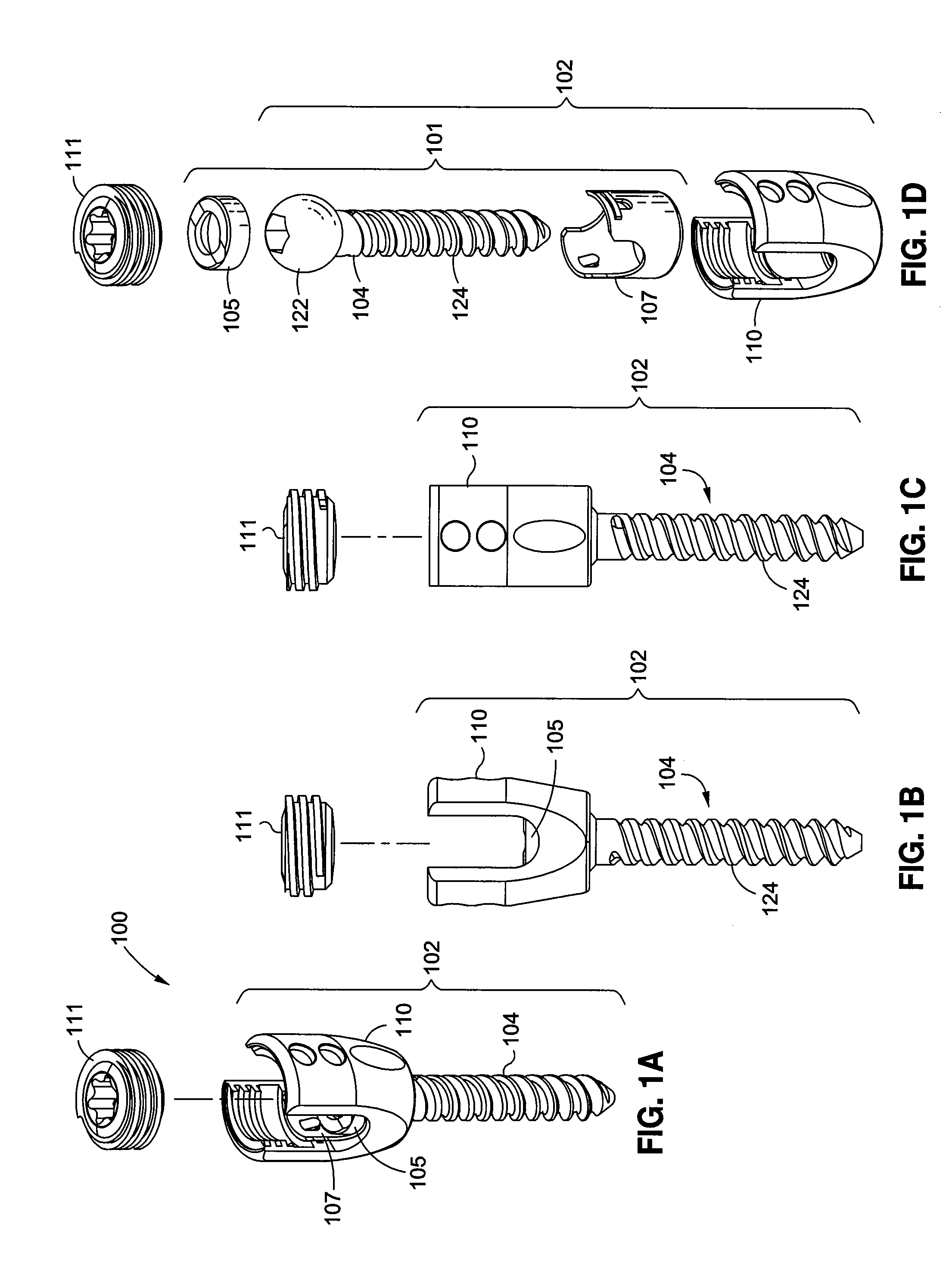
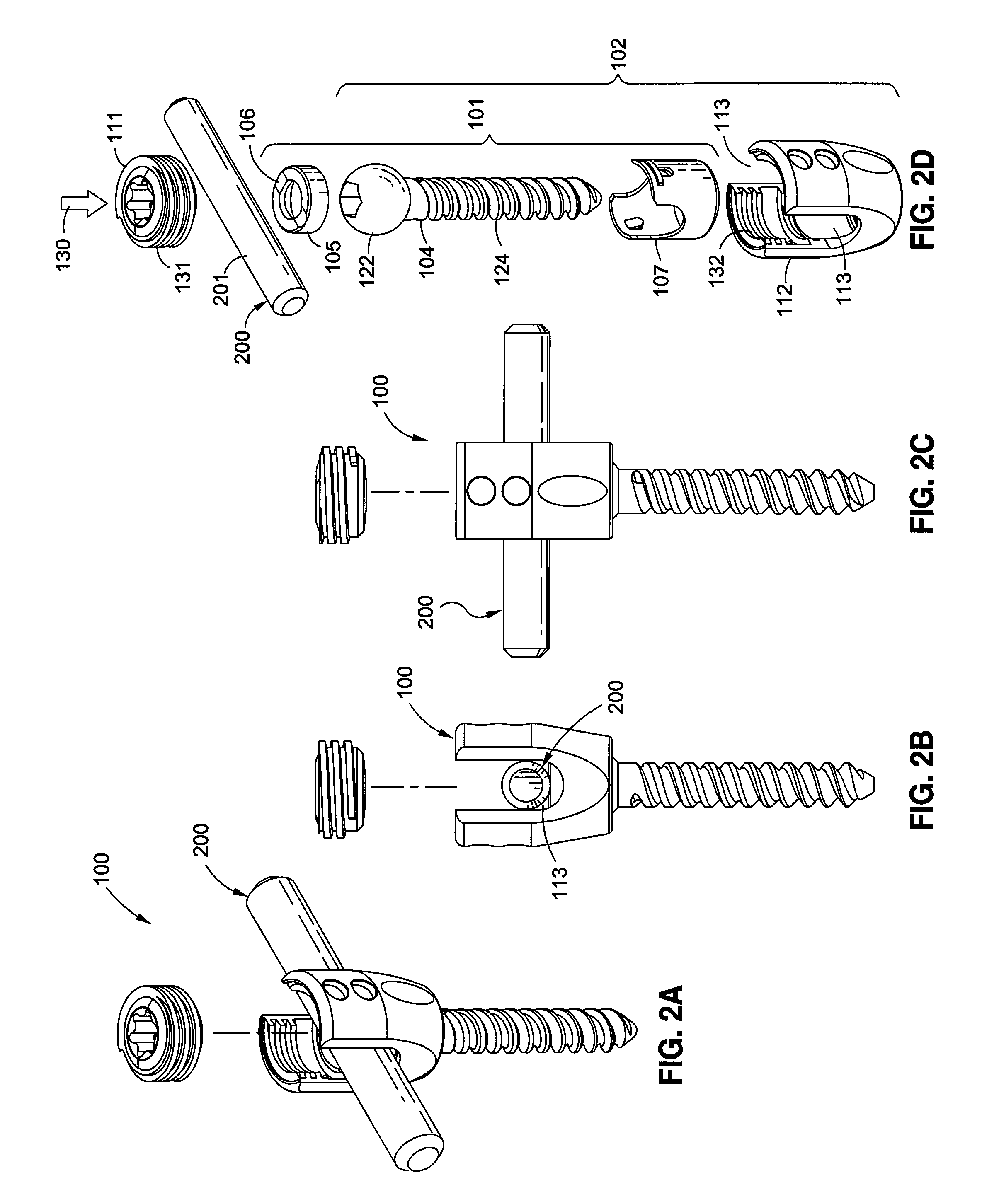
[0043]FIGS. 1A-1D show a perspective view, a side view, a front view, and an expanded view of a multi-axle pedicle screw (MAPS) 100 according to an embodiment of the present invention. The MAPS 100 may include a screw member 104, a compression member 105, a multifunctional adaptive member 107, a cradle 110, and a cap 111. Generally, the screw member 104 may have a spherical joint 122 and a threaded shaft 124, so that the spherical joint...


PUM


Abstract

The present invention may include a pedicle screw with a multifunctional adaptor, a strain reliever, and a dual-surface cap. The multifunctional adaptor may include a convex pivot ring for improving multi-axial movement and locking stability, an integrated locking mechanism for improving maneuverability, and an integrated compression member for improving the assembly process. The strain reliever may be formed along a neck of the pedicle screw for relieving mechanical stress asserted thereto, and thereby preventing a breakage thereof. The dual-surface cap may provide a slightly sloped surface for reducing the tension of the stabilizing rod. The present invention may also provide for a dynamic adaptor for flexibly connecting two stabilizing rods, which may be versatilely adapted to various pedicle screw configurations.

Description

BACKGROUND[0001]1. Field[0002]The present invention relates generally to the field of medical devices used in posterior spinal fixation surgery, and more particularly to pedicle screws and dynamic adaptors.[0003]2. Description of the Related Art[0004]Posterior spinal fixation surgery is a common procedure for patients who suffer from severe spinal conditions, such as spinal displacement, spinal instability, spinal degeneration, and / or spinal stenosis. Among other therapeutic goals, a successful posterior spinal fixation surgery may lead to the stabilization and fusion of several spinal bone segments of a patient. During a posterior spinal fixation surgery, a spine surgeon may insert several pedicle screws, which may function as anchoring devices, into several spinal bone segments of the patient to establish several anchoring points. Then, the spine surgeon may engage and secure a stabilizing rod, which may be an elongated member, to the several anchoring points to restrict or limit ...

Claims


Application Information

Patent Timeline
Patent Type & Authority Applications(United States)
IPC IPC(8): A61B17/70A61B17/86
CPCA61B17/7004A61B17/7023A61B17/864A61B17/863A61B17/7037
Inventor NIHALANI, RAJ
Owner SPINOFIX
Why Eureka
Try Eureka