Staged deployment devices and methods for transcatheter heart valve delivery systems

a technology of transcatheter delivery and prosthesis, applied in the field of prosthetic heart valve replacement, can solve the problems of difficult control of how much of the valve remains, impossible or best-case reshrinkage, and inability to cover the valve,

Active Publication Date: 2012-03-29
ST JUDE MEDICAL CARDILOGY DIV INC
View PDF3 Cites 67 Cited by
  • Summary
  • Abstract
  • Description
  • Claims
  • Application Information

AI Technical Summary

Benefits of technology

[0012]The first shaft may be fixedly connected to the frame, the catheter assembly further including an outer shaft connecting the carriage assembly to the distal sheath and at least partially surrounding the first shaft. The first shaft may be fixedly connected to the carriage assembly, and the catheter assembly may further include an outer shaft connecting the frame to the compartment and at least partially surrounding the first shaft. The operating handle may further include a deployment lock moveable between a locked position and an unlocked position, the deployment lock in the locked position preventing movement of the carriage assembly in the longitudinal direction within the movement space, the deployment lock in the unlocked position permitting movement of the carriage assembly in the longitudinal direction within the movement space. The carriage assembly may include a threaded rod and the operating handle may further include a deployment actuator threadedly engaged with the threaded rod such that rotation of the deployment actuator moves the carriage assembly in the longitudinal direction in the movement space.
[0013]The compartment may define a first length and the first intermediate position in the movement space may correspond to a travel distance of the carriage assembly, the travel distance being less than the first length. The collapsible prosthetic heart valve may define a second length and the travel distance may be about 80% to about 90% of the second length. The operating handle may further include a second resheathing lock moveable between a locked position and an unlocked position, the second resheathing lock in the locked position limiting movement of the carriage assembly in the longitudinal direction to a second intermediate position in the movement space, the second resheathing lock in the unlocked position permitting movement of the carriage assembly in the longitudinal direction beyond the second intermediate position. The collapsible prosthetic heart valve may define a length, the second intermediate position may define a first travel distance, and the first intermediate position may define a second travel distance, the first travel distance being about 40% to about 60% of the length and the second travel distance being about 80% to about 90% of the length. The frame may include a slot and the first resheathing lock may include a retractable locking member that is engaged in the slot when the first resheathing lock is in the locked position, an end of the slot defining the first intermediate position.

Problems solved by technology

Once a self-expanding valve has been fully deployed, it expands to a diameter larger than that of the sheath that previously contained the valve in the collapsed condition, making resheathing impossible, or difficult at best.
Despite the various improvements that have been made to the collapsible prosthetic heart valve delivery process, conventional delivery devices, systems, and methods suffer from some shortcomings.
For example, in conventional delivery devices for self-expanding valves, it is difficult to control how much of the valve remains in the sheath during a partial deployment, and the user may accidentally deploy the valve fully before verifying that the annulus end of the valve is in the optimal position in the patient's valve annulus, thereby taking away the opportunity to resheathe and reposition the valve.

Method used


Image

  • Staged deployment devices and methods for transcatheter heart valve delivery systems
  • Staged deployment devices and methods for transcatheter heart valve delivery systems
  • Staged deployment devices and methods for transcatheter heart valve delivery systems

Examples


Embodiment Construction

[0031]As used herein, the terms “proximal” and “distal” are to be taken as relative to a user using the disclosed delivery devices. “Proximal” is to be understood as relatively close to the user and “distal” is to be understood as relatively farther away from the user.

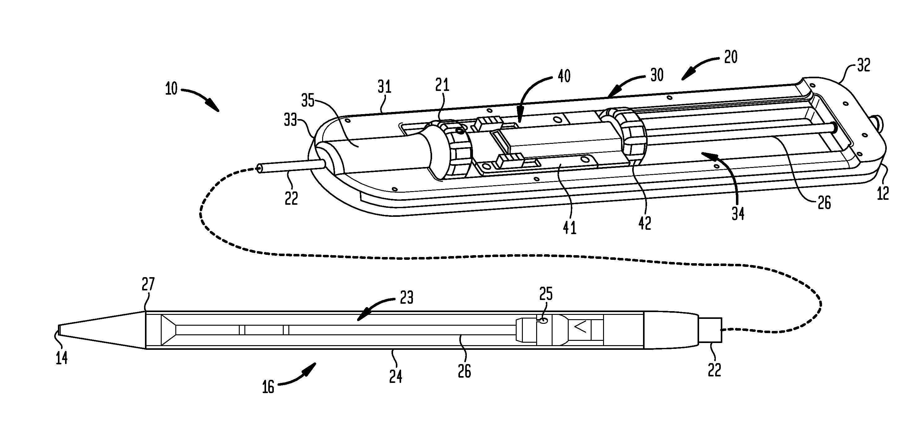
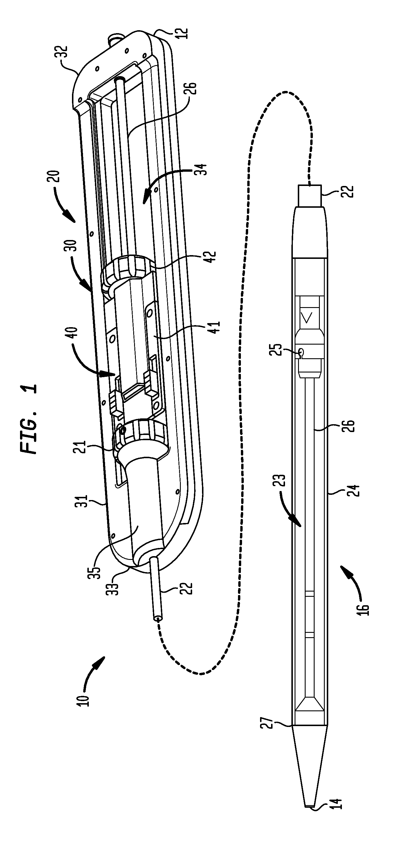
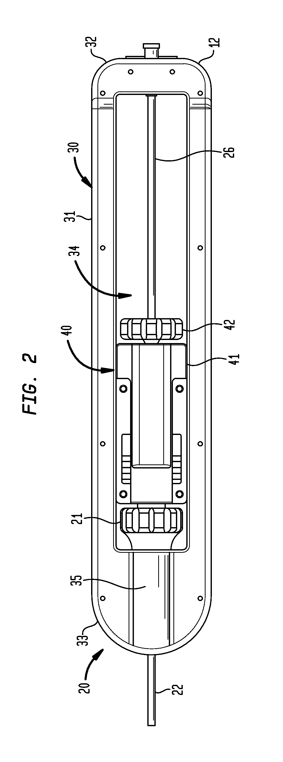
[0032]Referring now to FIGS. 1-4 to illustrate the structure and function of the present invention, an exemplary transfemoral delivery device 10 for a collapsible prosthetic heart valve (or other types of self-expanding collapsible stents) has a catheter assembly 16 for delivering the heart valve to and deploying the heart valve at a target location, and an operating handle 20 for controlling deployment of the valve from the catheter assembly. The delivery device 10 extends from a proximal end 12 to a distal tip 14. The catheter assembly 16 is adapted to receive a collapsible prosthetic heart valve (not shown) in a compartment 23 defined around an inner shaft 26 and covered by a distal sheath 24.

[0033]The inner shaft 2...


PUM


Abstract

A delivery device for a collapsible heart valve includes an operating handle, including a frame defining a movement space therein, a carriage assembly moveable within the movement space, and a first resheathing lock having a locked position and an unlocked position. The delivery device further includes a catheter assembly, including a first shaft around which a valve-receiving compartment is defined, the first shaft being fixedly connected to one of the frame or the carriage assembly, and a distal sheath operatively connected to the carriage assembly. The distal sheath is moveable between a closed condition adapted to maintain the valve in the compartment and an open condition adapted to fully deploy the valve. With the resheathing lock in the locked position, the distal sheath is unable to move to the open condition to fully deploy the valve.

Description

CROSS-REFERENCE TO RELATED APPLICATIONS[0001]This application claims the benefit of the filing date of U.S. Provisional Patent Application No. 61 / 376,425 filed Aug. 24, 2010, the disclosure of which is hereby incorporated herein by reference.BACKGROUND OF THE INVENTION[0002]The present invention is related to prosthetic heart valve replacement, and more particularly to devices, systems, and methods for transcatheter delivery of collapsible prosthetic heart valves.[0003]Prosthetic heart valves that are collapsible to a relatively small circumferential size can be delivered into a patient less invasively than valves that are not collapsible. For example, a collapsible valve may be delivered into a patient via a tube-like delivery apparatus such as a catheter, a trocar, a laparoscopic instrument, or the like. This collapsibility can avoid the need for a more invasive procedure such as full open-chest, open-heart surgery.[0004]Collapsible prosthetic heart valves typically take the form ...

Claims


Application Information

Patent Timeline
Patent Type & Authority Applications(United States)
IPC IPC(8): A61F2/24
CPCA61F2/2427A61F2/2436A61F2002/9534A61F2002/9517A61F2/966A61F2/9517A61F2/95A61F2002/9528
Inventor WANG, HUISUNTHOMAS, RALPH JOSEPH
Owner ST JUDE MEDICAL CARDILOGY DIV INC
Why Eureka
Try Eureka