Novel implant inserter having a laterally-extending dovetail engagement feature

a technology of engagement feature and implant, which is applied in the field of implant inserter with laterally extending dovetail engagement feature, can solve the problem of not being able to ensure that the anterior surface of the implant bottoms out on the inserter tip

Inactive Publication Date: 2012-03-29
DEPUY SYNTHES PROD INC
View PDF9 Cites 33 Cited by
  • Summary
  • Abstract
  • Description
  • Claims
  • Application Information

AI Technical Summary

Benefits of technology

[0009]The instrument of the present invention is advantageous over conventional inserter instruments having threads and other known grabber features, which sometimes need to withstand impaction and may move upon insertion of a bone anchor or instrument

Problems solved by technology

Conventional inserters with chamfer features also do not take advantage of dissimilar angles at the interface in more

Method used


Image

  • Novel implant inserter having a laterally-extending dovetail engagement feature
  • Novel implant inserter having a laterally-extending dovetail engagement feature
  • Novel implant inserter having a laterally-extending dovetail engagement feature

Examples


Embodiment Construction

[0039]The foregoing and other objects, features and advantages of the invention will be apparent from the following more particular description of preferred embodiments of the invention, as illustrated in the accompanying drawings in which like reference characters refer to the same parts throughout the different views. The same number appearing in different drawings represents the same item. The drawings are not necessarily to scale, with emphasis instead being placed upon illustrating the principles of the invention.

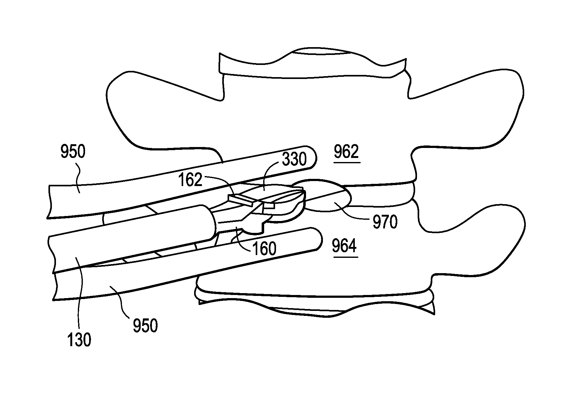
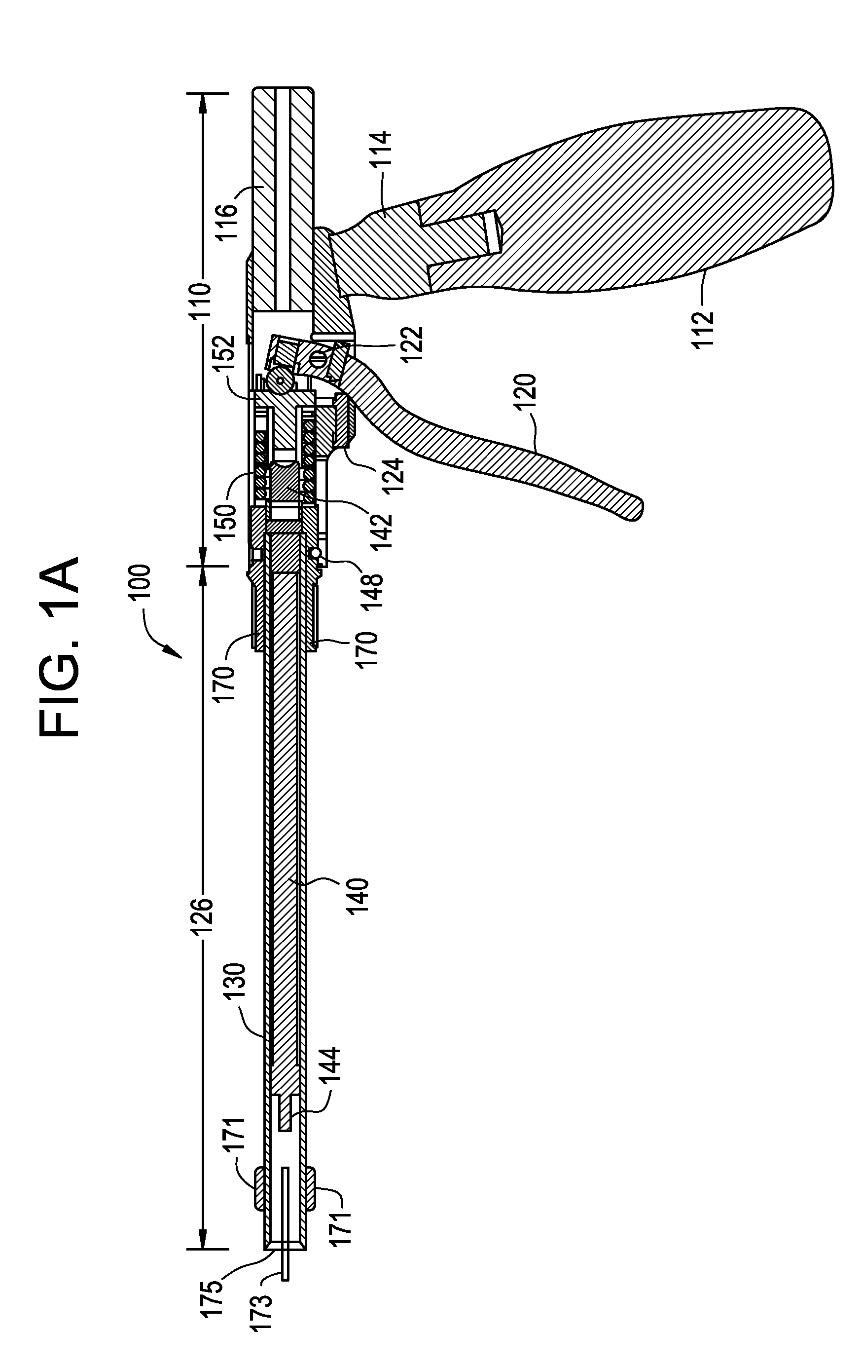
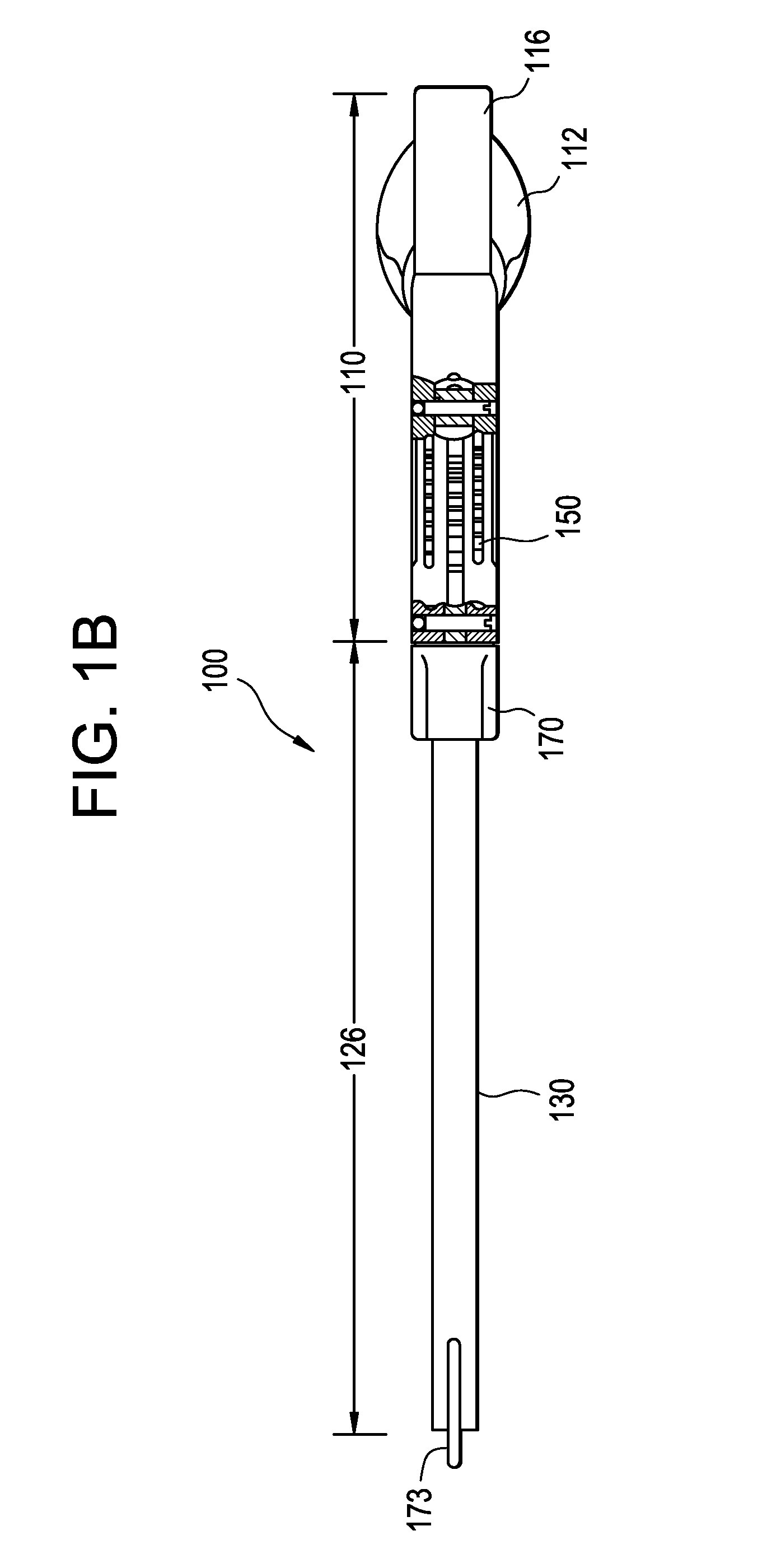
[0040]In general, the present invention is related to an apparatus and a method for safely inserting an implant into a spine. The implant can be an artificial disc or spinal fusion cage, or a spinal plate. Referring to FIGS. 1A and 1B, insertion instrument 100 is shown in a side cross-sectional view and a plan view, respectively. Insertion instrument 100 includes a frame or driver body assembly 110, an actuator assembly 126 and a forked inner shaft 160 (FIG. 2A-2C). In...


PUM


Abstract

A spinal implant inserter having a) an outer sleeve having a bore, and b) a forked inner shaft having a proximal rod and a pair of distal tynes extending therefrom, each distal tyne comprising an engagement feature having a laterally-extending dovetail feature. An assembly comprising the implant inserter and an implant having a pair of mating dovetail features.

Description

CONTINUING DATA[0001]This application claims priority from U.S. Ser. No. 61 / 385,959, filed on Sep. 23, 2010, and entitled “Stand Alone Intervertebral Fusion Device” (DEP6341USPSP), and is related to non-provisional U.S. Ser. No. ______, filed on even date, entitled “Stand Alone Intervertebral Fusion Device” (DEP6341USNP), the specifications of which are incorporated by reference in their entireties.[0002]This application claims priority from U.S. Ser. No. 61 / 466,309, filed on Mar. 22, 2011, and entitled “Novel Implant Inserter Having a Laterally-Extending Dovetail Engagement Feature” (DEP6392USPSP), the specification of which is incorporated by reference in its entirety.[0003]This application claims priority from U.S. Ser. No. 61 / 466,321, filed on Mar. 22, 2011, and entitled “Fusion Cage with In-Line Single Piece Fixation” (DEP6394USPSP), and is related to non-provisional U.S. Ser. No. ______, filed on even date, entitled “Fusion Cage with In-Line Single Piece Fixation” (DEP6394USNP...

Claims


Application Information

Patent Timeline
IPC IPC(8): A61F2/44
CPCA61B17/1631A61F2002/4687A61B17/80A61B17/808A61B17/8875A61B2017/0256A61F2/447A61F2/4611A61F2002/30387A61F2002/30578A61F2002/30823A61F2002/30904A61F2002/4475A61F2002/4627A61F2002/4629A61B17/1757A61B17/70A61B17/92A61F2/442A61F2002/30593A61B2017/00309A61F2/4455A61F2002/30782A61F2002/30507A61F2002/4635A61B17/88A61F2/46A61F2/44
Inventor GAMACHE, THOMASSORRENTI, MICHAEL D.
Owner DEPUY SYNTHES PROD INC
Why Eureka
Try Eureka