Vehicle drive

Inactive Publication Date: 2012-04-05
SCHMID EGON +1
View PDF15 Cites 9 Cited by
  • Summary
  • Abstract
  • Description
  • Claims
  • Application Information

AI Technical Summary

Benefits of technology

[0009]In a preferred embodiment, the axle has a differential. A differential affords the advantage of greater riding comfort. The differential is preferably arranged substantially in the center of the axle. This provides sufficient space on both sides for a wheel suspension system affording comfortable riding conditions. In the preferred embodiment, the drive transmission region is assigned to the differential. Preferred embodiments of this type may have a differential with an external gear rim via which the differential is driven, wherein the differential, in turn, drives the wheels of the axle, if appropriate vi

Problems solved by technology

A problem in the known prior art is the frequently insufficient mounting of the wheels, wherein it should be taken into consideration that, for example as prescribed by legal regulations, inval

Method used


Image

  • Vehicle drive
  • Vehicle drive

Examples


Embodiment Construction

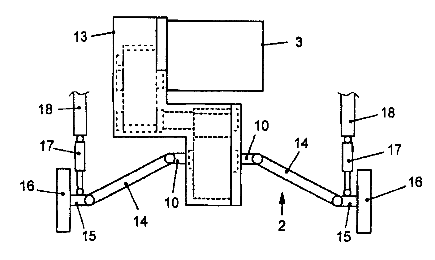
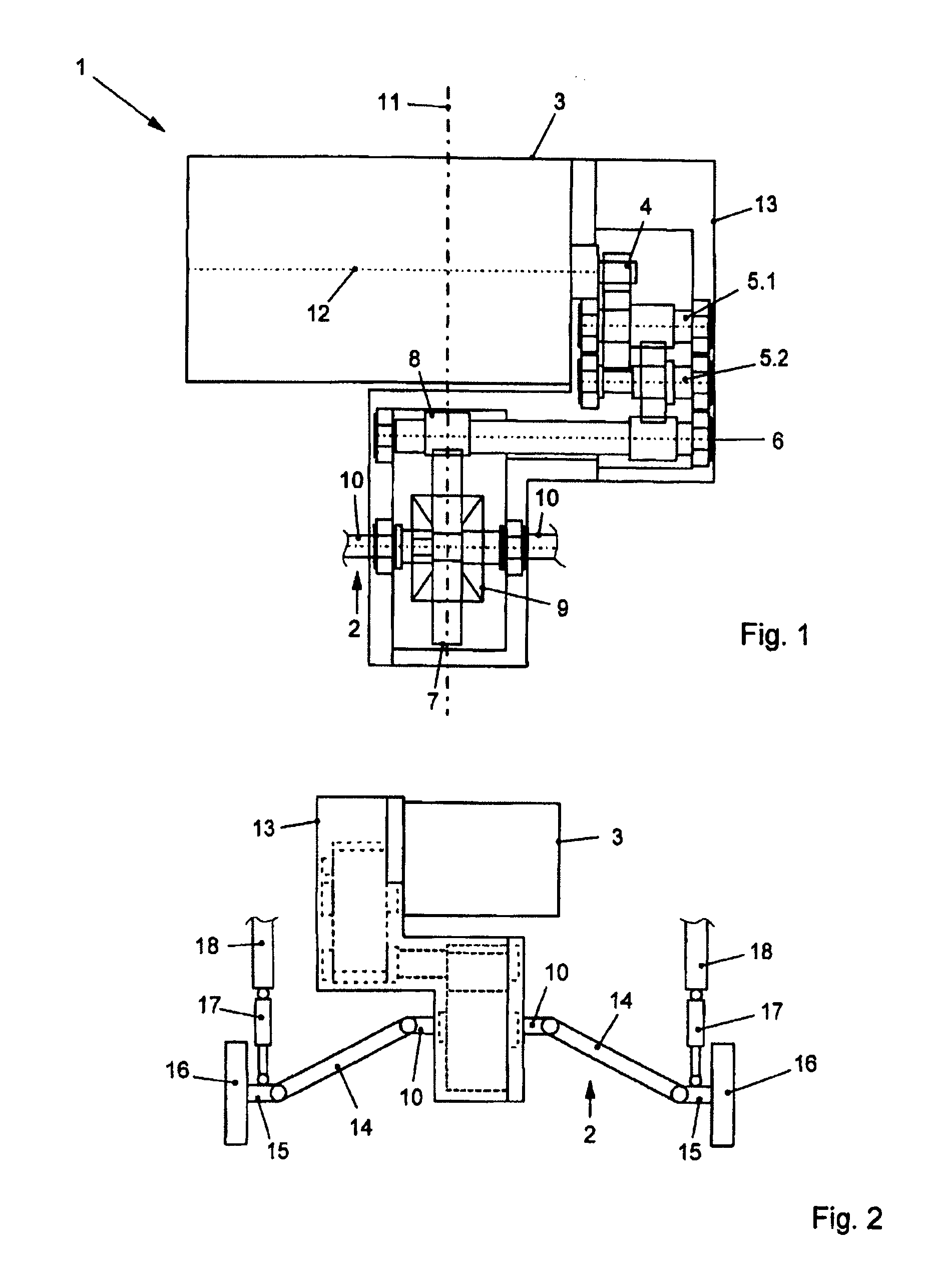
[0014]FIG. 1 shows a drive 1 according to the invention schematically in a sectional view. It should be noted that a part of the axle 2 of the drive 1 according to the invention is not shown in FIG. 1. The drive 1 according to the invention comprises an electric machine 3 which acts via an output shaft 4 on a first transmission shaft 5.1 which, in turn, acts on a second transmission shaft 5.2. The second transmission shaft 5.2 is in engagement with an intermediate shaft 6. The intermediate shaft 6 transmits the torque in a direction of the housing of the electric machine 3 in a direction parallel to the output shaft 4 of the electric machine 3. At the output end of the intermediate shaft 6, the torque is transmitted to a drive transmission region 7 of the axle 2. The output transmission region 7 is formed by an outer gear rim which is in engagement with a pinion 8 mounted on the intermediate shaft 6. Furthermore, FIG. 1 schematically shows a differential 9 which is driven by the dri...


PUM


Abstract

An invalid vehicle having a drive comprising an electric machine (3) which comprises an output shaft (4), and with an axle (2) which is operatively connected to the output shaft (4) via a drive transmission region (7) of the axle (2), wherein the output shaft (4) of the electric machine (3) is arranged substantially parallel to the axle (2), and the drive transmission region (7) is arranged substantially in the center of the axle (2).

Description

BACKGROUND OF THE INVENTION[0001]The invention relates to a drive for an invalid vehicle.[0002]Drives for electric invalid chairs have an electric machine which drives the rear axle. The electric machine has a comparatively large mass in comparison to the overall mass of the invalid chair and is therefore customarily arranged in the center of the invalid chair, in particular in the center with respect to the driven axle, in order to reduce the risk of the invalid chair tipping over. A transmission is arranged on that side of the electric machine on which the output shaft emerges out of the housing of the electric machine. The output shaft is operatively connected to the driven axle via the transmission. On both sides thereof, the driven axle has wheels which are thus driven by the electric machine.[0003]A problem in the known prior art is the frequently insufficient mounting of the wheels, wherein it should be taken into consideration that, for example as prescribed by legal regulat...

Claims


Application Information

Patent Timeline
IPC IPC(8): B60K1/00
CPCA61G5/04A61G2005/1078B60Y2200/84B60K17/22B60K2001/001B60K1/00A61G5/1078
Inventor SCHMID, EGONRICHTER, ALFRED
Owner SCHMID EGON
Why Eureka
Try Eureka