Electric bicycle hub unit, and electric bicycle including the hub unit

a technology for electric bicycles and hub units, which is applied in the direction of cycle equipment, cycle brakes, cycle brakes, etc., can solve the problems of always affecting the position of the motor, and achieve the effect of reducing the heat loss and increasing the heat loss

Inactive Publication Date: 2012-04-05
SANYO ELECTRIC CO LTD +1
View PDF5 Cites 16 Cited by
  • Summary
  • Abstract
  • Description
  • Claims
  • Application Information

AI Technical Summary

Benefits of technology

[0014]According to the present invention, the roller braking device is attached to the hub incorporating the motor and the deceleration mechanism which decelerates the rotation of the motor and transmits the decelerated rotation to the hub. In this case, the roller braking device is not attached to a portion of the hub located adjacent the motor which generates a greater amount of heat, but attached to the side surface of the hub located adjacent the deceleration mechanism which generates a smaller amount of heat. Thus, the roller braking device is located away from the heat generating component, so that the temperature rise of the roller braking device can be suppressed to ensure intended braking performance.

Problems solved by technology

In designing a power transmission system for the electric bicycle, the position of the motor is always a major issue.

Method used


Image

  • Electric bicycle hub unit, and electric bicycle including the hub unit
  • Electric bicycle hub unit, and electric bicycle including the hub unit
  • Electric bicycle hub unit, and electric bicycle including the hub unit

Examples


Embodiment Construction

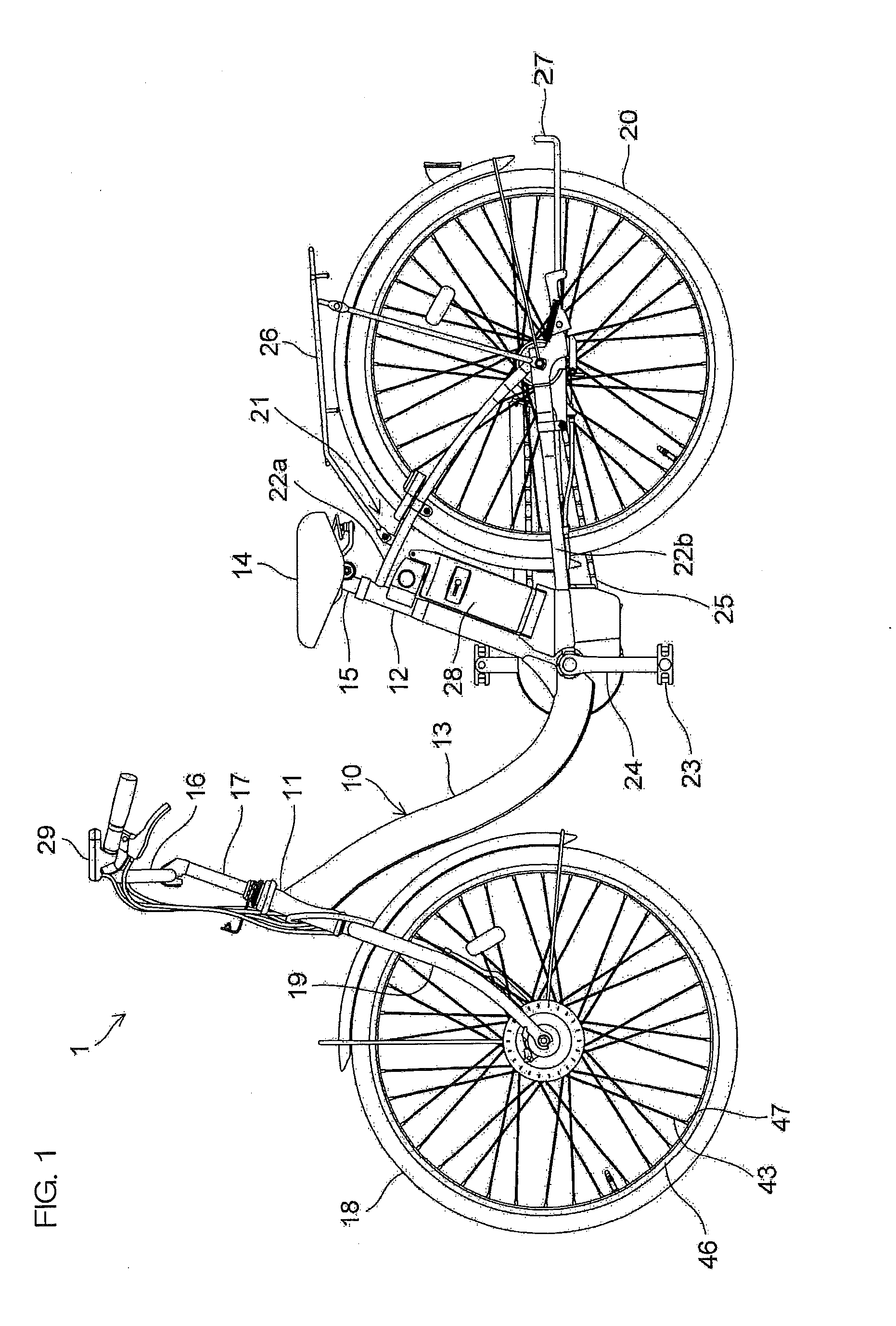
[0022]The overall construction of an electric bicycle will first be described with reference to FIG. 1.

[0023]The electric bicycle 1 is an electrically assisted bicycle adapted to assist a pedaling force by a motor. The electric bicycle 1 includes a frame 10, which includes a head tube 11 provided at a front end thereof, a seat tube 12 disposed at a rider riding position, and a down tube 13 connecting the head tube 11 to the seat tube 12. A seat post 15 having a saddle 14 provided at an upper end thereof is inserted in the seat tube 12 in a vertically adjustable manner. The head tube 11 rotatably retains a handle system 17 of a handle 16.

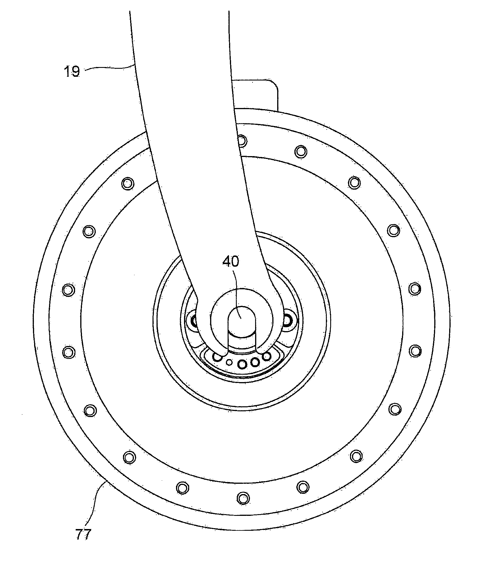
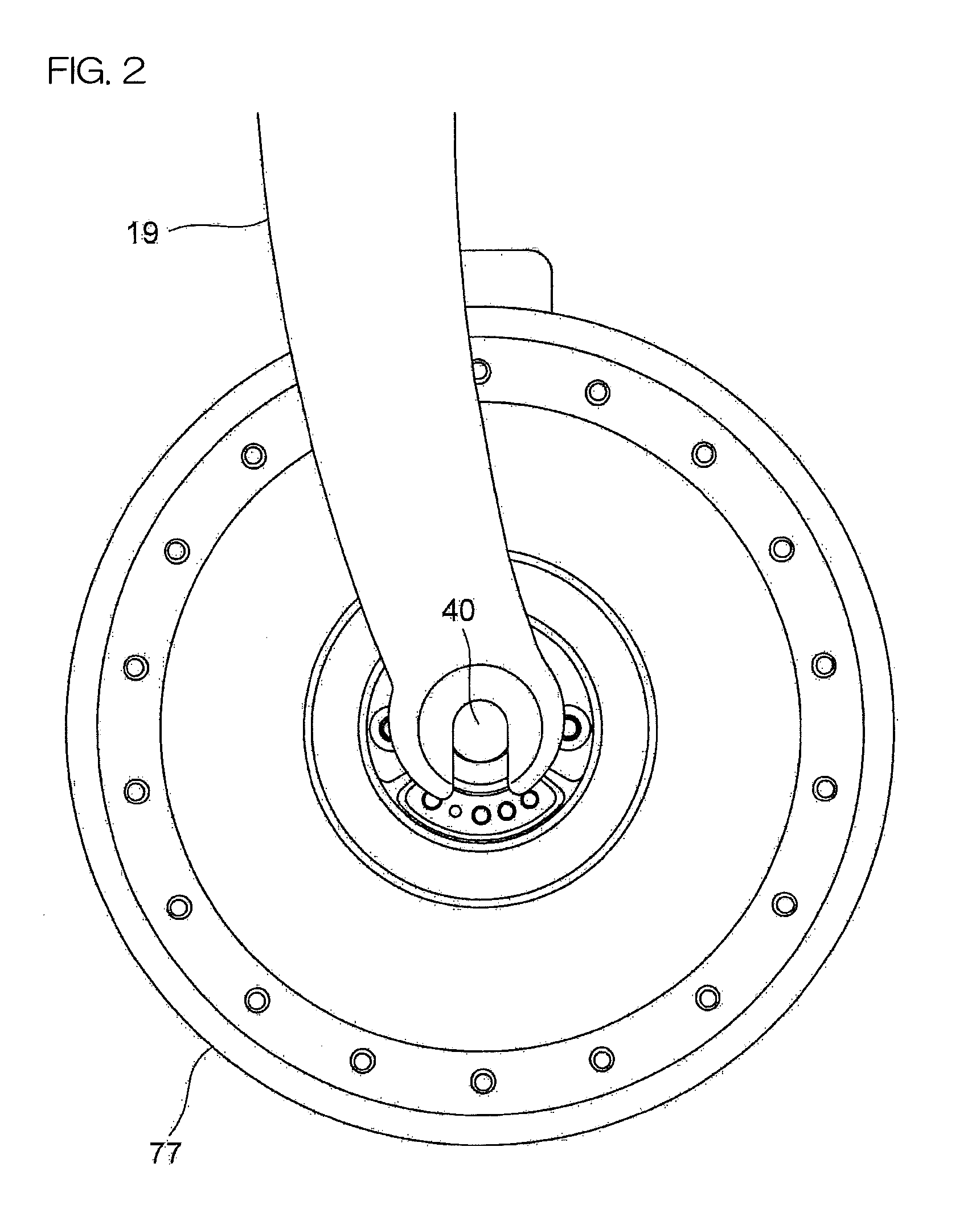
[0024]A front wheel 18 is supported by a front fork 19 connected to the handle system 17 in a nonrotatable manner. A rear wheel 20 is supported by a rear fork 21, which includes a seat stay 22a extending rearward from the upper end of the seat tube 12, and a chain stay 22b extending rearward from a lower end of the seat tube 12.

[0025]A crank 24 inclu...


PUM


Abstract

In an electric bicycle, an assist driving force is generated by a hub unit mounted in a front wheel. The hub unit includes a hub including a hub casing and a lid closing an open end of the hub casing, a motor, and a planetary gear deceleration mechanism which decelerates rotation of the motor and transmits the decelerated rotation to the hub. The motor is located adjacent the hub casing, and the planetary gear deceleration mechanism is located adjacent the lid. A roller braking device is attached to the lid.

Description

TECHNICAL FIELD[0001]The present invention relates to an electric bicycle hub unit, and to an electric bicycle including the hub unit.BACKGROUND ART[0002]Electric bicycles which are driven by a motor employing a battery as a power source (including electrically assisted bicycles adapted to assist a pedaling force by a motor) ensure easy driving when carrying a heavy load or traveling uphill. Therefore, more and more consumers selectively buy such electric bicycles. An exemplary electric bicycle is disclosed in JP-A-HEI6 (1994)-107266.[0003]In designing a power transmission system for the electric bicycle, the position of the motor is always a major issue. JP-A-2005-335535 and JP-A-2009-12627 propose to incorporate the motor together with a deceleration mechanism in a front wheel hub or a rear wheel hub.[0004]The electric bicycle generally has an increased mass with the battery mounted therein, thereby requiring a greater braking force. JP-C-4073929 and JP-A-2006-347412 disclose roll...

Claims


Application Information

Patent Timeline
Patent Type & Authority Applications(United States)
IPC IPC(8): B62K11/02B62L5/18
CPCB62M6/65B62M23/02B62M11/16
Inventor NISHIMORI, MASATO
Owner SANYO ELECTRIC CO LTD
Why Eureka
Try Eureka